


This blog post is the fifth of a multi-part series of posts where I will explore various peripherals of the ESP32 using the embedded Rust embassy framework.
Prior posts include (in order of publishing):
Introduction
Hardware timers while relatively simple circuits are really effective in several applications in embedded. Timer peripherals are effective in timing both software and hardware events. Timers also have features that allow the generation of hardware waveforms (Ex. PWM). In this post, I'll use embassy to measure the width of the pulse for two different signals. The resulting pulse width value will be printed on the console.
The square waves used in this post will be generated using the Wokwi custom external block. In general, this type of measurement would be useful as it emulates the behavior of applications that include tachometers or anemometers. Tachometers and anemometers generate square wave signals that are proportional to the speed of rotation. With some calculations, and depending on the application, the provided code can be expanded to provide frequency and/or rpm values.
📚 Knowledge Pre-requisites
To understand the content of this post, you need the following:
- Basic knowledge of coding in Rust.
💾 Software Setup
All the code presented in this post is available on the apollolabs ESP32C3 git repo. Note that if the code on the git repo is slightly different then it means that it was modified to enhance the code quality or accommodate any HAL/Rust updates.
Additionally, the full project (code and simulation) is available on Wokwi here.
🛠 Hardware Setup
Materials
-
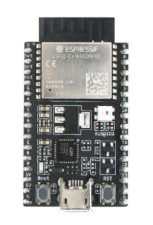
Square Wave Generator/Pulse Generator: This can take many forms in real hardware though since I'm using Wokwi, there is the custom chip feature that allows me to generate square waves.
🔌 Connections
📝 Note
All connection details are also shown in the Wokwi example.
Connections include the following:
Gpio0 wired to the top pin of the breakout custom chip.
Gpio1 wired to the bottom pin of the breakout custom chip.
👨🎨 Software Design
The square wave signal is going to be fed into the ESP32 as an input. For the purpose of this post, the code will measure the widths of the pulses in each square wave. The custom chip is designed such that one wave generates pulses that are 10ms wide and another that are 25ms wide. To measure the pulse width, the algorithm in this post needs to determine the time elapsed between every positive edge and the negative edge that follows.
Following the configuration of the pins and the device, for each pin the follow steps are taken:
awaita positive edge transition.Capture timer instant.
awaitnegative edge transition.Calculate then print the duration of the pulse.
Go back to step 1
Let's now jump into implementing this logic.
🚨 Important Note
The custom chip block in Wokwi has its own internal code that generates the square waves/pulses. There is a tab in the project where one can look at the source code. However, how to create and code a custom block is not part of this post. For the interested in creating custom chips in Wokwi I recommend checking out the chips api documentation.
👨💻 Code Implementation
📥 Crate Imports
In this implementation, the following crates are required:
The
embassy_executorcrate to import the embassy executor.The
esp32c3-halcrate to import the necessary ESP32C3 abstractions.The
esp_backtracecrate needed to define panic behavior.The
embassy_timecrate to obtain timer abstractions.The
embedded_hal_asynccrate to obtain digital pinWaitabstractions.The
esp_backtracecrate needed to define panic behavior.
use embassy_executor::Spawner;
use embassy_time::Instant;
use embedded_hal_async::digital::Wait;
use esp32c3_hal::gpio::{AnyPin, Input, PullUp};
use esp32c3_hal::{clock::ClockControl, embassy, peripherals::Peripherals, prelude::*, IO};
use esp_backtrace as _;
💓 The Pulse Timer Task
There are two pulse timer tasks, one for each pin. Both will replicate the same behavior except for two different pins. The pulse timer task is expected to await for pin edges to time the pulse width. These are the required steps:
1️⃣ Create a Pulse Timer Task: Tasks are marked by the #[embassy_executor::task] macro followed by a async function implementation. The task created is referred to as pulse1_timer task defined as follows:
#[embassy_executor::task]
async fn pulse1_timer(mut pin: AnyPin<Input<PullUp>>) {
There is a similar task that will have the exact same code called pulse2_timer .
🔁 Task Loop
1️⃣ Wait for rising edge on pin: The first thing we need to do is await the incoming pulse to become high. For that, there exists a wait_for_high method implementation for the Wait trait in the embedded-hal-async. wait_for_high is an async function that resolves into a Future if its waiting on a condition. Otherwise, we get a Result . We call wait_for_high on pin as follows:
pin.wait_for_high().await.unwrap();
2️⃣ Capture the time instant: now that the signal turned high, a timer needs to be started to time the duration of the pulse. Using the new method from the Instant abstraction in the embassy-time crate allows the capture of the current time instant. We can bind the captured instant to an inst variable as follows:
let inst = Instant::now();
3️⃣ Wait for falling edge on pin: Now all we need to do is await the incoming signal to become low marking the end of the pulse. Now instead we use a wait_for_low method implementation for the Wait trait in the embedded-hal-async. We call wait_for_low on pin as follows:
pin.wait_for_low().await.unwrap();
4️⃣ Calculate and print duration: To calculate the Duration, Instant has a checked_duration_since method that takes two Instants and calculates a Duration. As such, we have to calculate the difference between the current Instant (after falling edge) and inst that was captured after a rising edge. Also using the as_millis Duration method, we can extract the time in milliseconds and print as follows:
// Calculate Duration
let pwidth = Instant::checked_duration_since(&Instant::now(), inst).unwrap();
// Print Duration
esp_println::println!("Sq Wave 1 Pulse Width is {}ms", pwidth.as_millis());
📱 The Main Task
The start of the main task is marked by the following code:
#[embassy_executor::main]
async fn main(spawner: Spawner)
The following steps will mark the tasks performed in the main task.
1️⃣ Obtain a handle for the device peripherals & system clocks: In embedded Rust, as part of the singleton design pattern, we first have to take the device peripherals. This is done using the take() method. Here I create a device peripheral handler named peripherals , a system peripheral handler system, and a system clock handler clocks as follows:
let peripherals = Peripherals::take();
let system = peripherals.SYSTEM.split();
let clocks = ClockControl::boot_defaults(system.clock_control).freeze();
2️⃣ Initialize Embassy Timers for the ESP32C3: In embassy, there exists an init function that takes two parameters. The first is system clocks and the second is an instance of a timer. Under the hood, what this function does is initialize the embassy timers. As such, we can initialize the embassy timers as follows:
embassy::init(
    let timer_group0 = esp32c3_hal::timer::TimerGroup::new(peripherals.TIMG0, &clocks);
    embassy::init(&clocks, timer_group0.timer0);
3️⃣ Instantiate and Create Handle for IO: We need to configure the signal input pins as inputs and obtain handlers for them. Before we can obtain any handles we need to create an IO struct instance. The IO struct instance provides a HAL-designed struct that gives us access to all gpio pins thus enabling us to create handles for individual pins. This is similar to the concept of a split method used in other HALs (more detail here). We do this by calling the new() instance method on the IO struct as follows:
let io = IO::new(peripherals.GPIO, peripherals.IO_MUX);
Note how the new method requires passing the GPIO and IO_MUX peripherals.
4️⃣ Obtain a handle and configure the signal input pins: The signal inputs are connected to pins 0 and 1 (gpio0 and gpio1) as stated earlier. Additionally, since the pin is driven by an external signal that has known states it can be configured as floating. A floating input can be configured for the pin using the into_floating_input() method as follows:
let del_but = io.pins.gpio2.into_floating_input().degrade();
Note that we are using the degrade method which "degrades" the pin type into a generic AnyPin type that is required to pass to the button_press task.
5️⃣ Spawn Pulse Timer Tasks: now that configuration is done, we can kick off both the pulse1_timer and pulse2_timer tasks. This is done using the spawn method as follows:
spawner.spawn(pulse1_timer(pulse1)).ok();
spawner.spawn(pulse2_timer(pulse2)).ok();
📱 Full Application Code
Here is the full code for the implementation described in this post. You can additionally find the full project and others available on the apollolabs ESP32C3 git repo. Also, the Wokwi project can be accessed here.
#![no_std]
#![no_main]
#![feature(type_alias_impl_trait)]

use embassy_executor::Spawner;
use embassy_time::{Instant, Duration};
use embedded_hal_async::digital::Wait;
use esp32c3_hal::gpio::{AnyPin, Input, Floating};
use esp32c3_hal::{clock::ClockControl, embassy, peripherals::Peripherals, prelude::*, IO};
use esp_backtrace as _;

#[embassy_executor::task]
async fn pulse1_timer(mut pin: AnyPin<Input<Floating>>) {
    loop {
        // Wait for rising edge
        pin.wait_for_high().await.unwrap();
        // Capture time instant at rising edge
        let inst = Instant::now();
        // Wait for falling edge
        pin.wait_for_low().await.unwrap();
        // Calculate Duration
        let pwidth = Instant::checked_duration_since(&Instant::now(), inst).unwrap();
        // Print Duration
        esp_println::println!("Sq Wave 1 Pulse Width is {}ms", pwidth.as_millis());
        // Uncomment below line to reduce console print frequency
        // Timer::after(Duration::from_millis(1000)).await;
    }
}

#[embassy_executor::task]
async fn pulse2_timer(mut pin: AnyPin<Input<Floating>>) {
    loop {
        // Wait for rising edge
        pin.wait_for_high().await.unwrap();
        // Capture time instant at rising edge
        let inst = Instant::now();
        // Wait for falling edge
        pin.wait_for_low().await.unwrap();
        // Calculate Duration
        let pwidth = Instant::checked_duration_since(&Instant::now(), inst).unwrap();
        // Print Duration
        esp_println::println!("Sq Wave 1 Pulse Width is {}ms", pwidth.as_millis());
        // Uncomment below line to reduce console print frequency
        // Timer::after(Duration::from_millis(1000)).await;
    }
}

#[main]
async fn main(spawner: Spawner) {
    let peripherals = Peripherals::take();
    let system = peripherals.SYSTEM.split();
    let clocks = ClockControl::boot_defaults(system.clock_control).freeze();

    // Initialize Embassy with needed timers
    let timer_group0 = esp32c3_hal::timer::TimerGroup::new(peripherals.TIMG0, &clocks);
    embassy::init(&clocks, timer_group0.timer0);

    // This line is for Wokwi only so that the console output is formatted correctly
    esp_println::print!("\x1b[20h");

    // Inititalize and configure pins
    // Acquire Handle to IO
    let io = IO::new(peripherals.GPIO, peripherals.IO_MUX);
    // Configure pins as pull up input and degrade
    let pulse1 = io.pins.gpio0.into_floating_input().degrade();
    let pulse2 = io.pins.gpio1.into_floating_input().degrade();

    // Spawn pulse measurement tasks
    spawner.spawn(pulse1_timer(pulse1)).ok();
    spawner.spawn(pulse2_timer(pulse2)).ok();
}
Conclusion
In this post, a timer application measuring square wave pulse durations was created. The application leverages the Timer peripherals for the ESP32C3 microcontroller. The code was created leveraging the embassy framework. Have any questions? Share your thoughts in the comments below 👇.