


This blog post is the second of a multi-part series of posts where I explore various peripherals in the STM32F401RE microcontroller using embedded Rust at the PAC level.
Prior posts include (in order of publishing):
🎬 Introduction
In embedded development with Rust, there exist several options (or abstraction levels) at which one can develop code. These abstractions are represented in the form of crates and include the peripheral access crate (PAC), the hardware abstraction layer (HAL), and board crates. In a past series, I explored coding strictly at the HAL level for the STM32F4. It was apparent that, in a HAL, except for some detail, one does not need much reliance on the microcontroller reference manuals. Especially if the HAL is well documented. HALs are also more portable as they can represent a wider base of devices with a single code base.
Compared to HALs, PACs enable lower-level access to hardware peripherals, such as sensors, actuators, and communication interfaces, on microcontroller-based devices. The PAC is much closer to the register level and allows for much control but at the cost of portability. With the PAC, one can perform tasks such as configuring and controlling peripherals, reading and writing data and triggering events or interrupts. Consequently, PAC coding needs much more reliance on controller reference manuals to understand how registers should be manipulated.
One might wonder why might it be necessary to develop at the PAC level. In an ideal world, we wouldn't need to. Nevertheless, there are at least a couple of reasons that I can think of at this point that would require PAC development knowledge. One is if you are dealing with a new device (or devices) and want to create a HAL for it/them. However, another is that even current HALs don't necessarily implement all features for devices. As such one would need to supplement/mix their HAL code with PAC code.
In this post, and the upcoming series of posts, I will be working with the STM32F401 microcontroller to present and walk through examples for different peripherals. I will be exclusively working at the PAC level. In particular, I will be using the PAC crate I generated in the first post in this series. Recall that when generating the PAC using svd2rust, the main APIs exposed are read, write, and modify . Which API can be used depends on what the device allows us to do with a register field. In this post, I will be starting out with an example of the GPIO peripheral. We'll see how we can configure GPIO, read inputs, and manipulate output at the PAC.
📚 Knowledge Pre-requisites
To understand the content of this post, you need the following:
Basic knowledge of coding in Rust.
Familiarity with the basic template for creating embedded applications in Rust.
💾 Software Setup
All the code presented in this post in addition to instructions for the environment and toolchain setup is available on the apollolabsdev Nucleo-F401RE git repo. Note that if the code on the git repo is slightly different then it means that it was modified to enhance the code quality or accommodate any Rust updates.
🛠 Hardware Setup
🧰 Materials
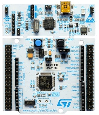
🔌 Connections
There will be no need for external connections. On-board connections will be utilized and include the following:
An LED is connected to pin PA5 on the microcontroller. The pin will be used as an output.
A user button is connected to pin PC13 on the microcontroller. The pin will be used as input.
👨🎨 Software Design
In the application developed in this post, I want to simply turn on the LED on the detection of a button press. That means that we need to configure PC13 (connected to the button) as input and be able to read its value. Additionally, we need to configure PA5 (connected to the LED) as output and be able to control it (write a value to it). To do that, in the STM32 there are 8 different registers for the GPIO peripheral:
MODER (GPIO port mode register): This register sets the mode of operation for each GPIO pin. It determines whether the pin is an input, output, or alternate function.
OTYPER (GPIO port output type register): This register sets the output type for each GPIO pin. It can be either open-drain or push-pull.
OSPEEDR (GPIO port output speed register): This register sets the speed at which the output signals change for each GPIO pin. It can be low, medium, fast, or high speed.
PUPDR (GPIO port pull-up/pull-down register): This register sets the pull-up or pull-down resistor for each GPIO pin.
IDR (GPIO port input data register): This register holds the digital values of the input pins on the GPIO port.
ODR (GPIO port output data register): This register holds the digital values of the output pins on the GPIO port.
BSRR (GPIO port bit set/reset register): This register is used to set or reset the output pins on the GPIO port.
LCKR (GPIO port configuration lock register): This register is used to lock the configuration of the GPIO pins to prevent accidental changes.
For our purposes, we won't be needing all of the registers, but rather only a subset. We'll be looking into only the ones we need. More detail will follow in the code implementation.
Be mindful that the STM32 GPIO peripherals are clock gated. This means that by default the GPIO peripherals are turned off since their clock is disabled. As such, we first need to enable the clock to the GPIO peripheral so that we can "turn it on" so to speak. This will be done via the RCC_AHB1ENR register.
👨💻 Code Implementation
📥 Crate Imports
In this implementation, three crates are required as follows:
The
cortex_m_rtcrate for startup code and minimal runtime for Cortex-M microcontrollers.The
panic_haltcrate to define the panicking behavior to halt on panic.The
stm32f4xx_paccrate to import the STM32F401 microcontroller device PAC API that was created in the first post in this series.
use cortex_m_rt::entry;
use panic_halt as _;
use stm32f401_pac as pac;
Throughout this series, unless we require any special constructs, these imports are more or less going to probably remain the same.
🎛 Peripheral Configuration Code
Ahead of our application code, peripherals are configured through the following steps:
1- Obtain a Handle for the Device Peripherals: In embedded Rust, as part of the singleton design pattern, we first have to obtain a handle for the PAC-level device peripherals. This is done using the take() method. Here I create a device peripheral handler named dp as follows:
let dp = pac::Peripherals::take().unwrap();
Using this handle, I will be accessing the rest of the peripherals in the device.
2- Enable Clock to GPIO: There are two GPIO peripheral blocks that will be used in our code. First is GPIOA that pin PA5 belongs, and the second is GPIOC which pin PC13 belongs. As a result, the clock for each of those blocks needs to be enabled so that we can use them. As mentioned earlier, this is done using the RCC_AHB1ENR register which has the following mapping (obtained from the STM32F4 reference manual):
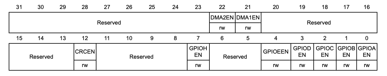
Note that GPIOA is enabled via bit 0 and GPIOC via bit 2. The reference manual requires that we modify the value to 1 or "high" to enable the clock. Note also how under some fields there is the "rw" annotation. This indicates that we can both read and write to these bits. This also means that the PAC will expose all three methods to us read, write, and modify for the bits with the "rw" annotation. As such, to enable the clocks we need to write do different fields as follows:
dp.RCC
  .ahb1enr
  .write(|w| w.gpioaen().set_bit().gpiocen().set_bit());
write provides a closure with a token to access the individual register fields and then apply methods to manipulate them. Note how we are writing to the gpioaen and gpiocen fields in the ahb1enr register. For each of the fields the set_bit() method is being applied. These are all methods exposed by the PAC and the cool thing is that they follow the same naming convention as the datasheet. The svd2rust documentation provides more insight on the use of the methods as well.
3- Configure PA5 as Output: Here we need to configure the LED pin as a push-pull output so that we can control it. This is done through the GPIOA_MODER and GPIOA_OTYPER . MODER registers exist for every GPIO port and have the following mapping:
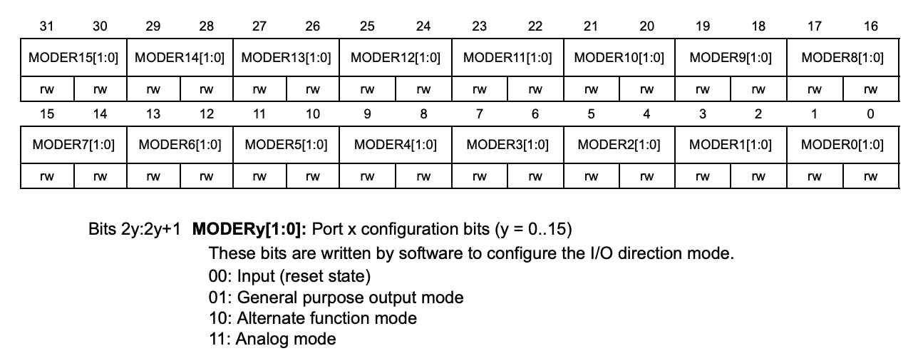
Note that each port can have up to 15 pins and each pin is represented by 2 bits, from MODER0 to MODER15. Additionally, by default, the pins are in the input state coming in from reset. This means we only need to change the configuration if we want the pin to operate in a different mode than input.
Looking at the register mapping, the MODER5 field in GPIOA_MODER controls the mode of PA5. To configure the PA5 as output the value of "01" needs to be written into bits 11 and 10 of the register. This results in the following line of code:
dp.GPIOA.moder.write(|w| unsafe { w.moder5().bits(0b01) });
Here the code is considered unsafe because we could be writing a reserved bit pattern into the register field.
The OTYPER register on the other hand allows us to control how the output pin operates. There are two options; push-pull and open-drain. The OTYPER register has the following mapping:
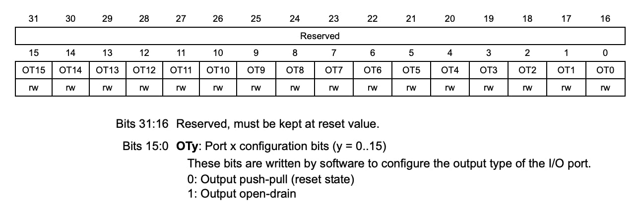
Note that by default, output pins are configured as push-pull which is what we need. This means we don't need to change anything here.
4- Configure PC13 as Input: I put in this step for the sake of completion since there isn't really anything that needs to be done here. In the earlier section, if you note the MODER mapping, all pins are configured as input by default. Though if one desires, there is an option of configuring input pins with an internal pull-up or pull-down resistor through the PUPDR register. This is to provide a default state when the pin is left floating. We don't need to do this here since a resistor already exists external to the pin on the board I'm using.
This is it for configuration.
📱 Application Code
Following the design described earlier, all we need to do is continuously read the PC13 input and then control the PA5 output accordingly. To read PC13 we need to access the IDR register for GPIOC specifically the GPIOC_IDR which has the following mapping:
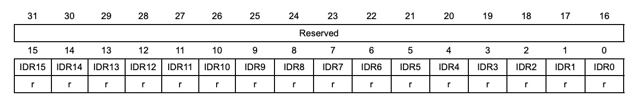
Note how there is a single-bit field for each of the 15 pins in a GPIO port. Additionally, all fields are read-only, in which the PAC would expose only the read API. The state of PC13 is captured in bit 13 of the IDR resulting in the following code to continuously read PC13 and check if its low (button press state):
loop {
    // Read PC13 Input Value
    if !dp.GPIOC.idr.read().idr13().bit() {
        // Code if PC13 Low
    } else {
        // Code if PC13 High
    }
}
Now if PC13 is low, we need to turn on the LED by making PA5 go high. Note that PA5 defaults to low so there wasn't any need to initialize it. Controlling output can be done via two registers either the BSRR register or the ODR register. The difference is that the BSRR allows for what is referred to as atomic operation when modifying the output pins. This is something that we're not too concerned about in this particular application. For now, I'm going to elect to use the ODR register to modify the output, and it has the following mapping:
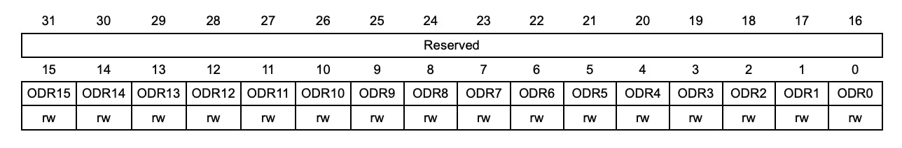
You can maybe already notice that the ODR mapping looks more or less like the IDR with one small difference. The difference is that the fields all now have read and write options. Here we need to access GPIOA_ODR bit number 5 to control PA5 resulting in the following:
loop {
    if !dp.GPIOC.idr.read().idr13().bit() {
        dp.GPIOA.odr.write(|w| w.odr5().set_bit());
    } else {
        dp.GPIOA.odr.write(|w| w.odr5().clear_bit());
    }
}
This concludes our application!
📀 Full Application Code
Here is the full code for the implementation described in this post. You can additionally find the full project and others available on the apollolabsdev Nucleo-F401RE git repo.
#![no_std]
#![no_main]

// Imports
use cortex_m_rt::entry;
use panic_halt as _;
use stm32f401_pac as pac;

#[entry]
fn main() -> ! {
    // Setup handler for device peripherals
    let dp = pac::Peripherals::take().unwrap();

    //Enable Clock to GPIOA & GPIOC
    dp.RCC
        .ahb1enr
        .write(|w| w.gpioaen().set_bit().gpiocen().set_bit());

    //Configure PA5 as Output
    dp.GPIOA.moder.write(|w| unsafe { w.moder5().bits(0b01) });

    // Application Loop
    loop {
        // Read PC13 Input Value
        if !dp.GPIOC.idr.read().idr13().bit() {
            // If high then set PA5 output to High (Turn on LED)
            dp.GPIOA.odr.write(|w| w.odr5().set_bit());
        } else {
            // If low then set PA5 output to Low (Turn off LED)
            dp.GPIOA.odr.write(|w| w.odr5().clear_bit());
        }
    }
}
🔬 Further Experimentation/Ideas
Look into the reference manual and figure out how to use the
BSRRinstead of theODRto controlPA15.Use the button to toggle the output instead. Note that you might experience some button-bouncing effects though.
Connect multiple LED outputs and create different LED lighting patterns. You can use the button to switch between patterns.
Create a Blinky example. To introduce a delay, since we haven't done timers yet, use a loop with a certain amount of iterations. This might need some trial and error to figure out the appropriate number of iterations.
Conclusion
In this post, an LED control application was created in Rust leveraging a GPIO peripheral and exclusively a peripheral access crate (PAC). The application was developed for an STM32F401RE microcontroller deployed on the Nucleo-F401RE development board. Have any questions? Share your thoughts in the comments below 👇.