


This blog post is the fourth of a multi-part series of posts where I explore various peripherals in the STM32F401RE microcontroller using embedded Rust at the HAL level. Please be aware that certain concepts in newer posts could depend on concepts in prior posts.
Prior posts include (in order of publishing):
- STM32F4 Embedded Rust at the HAL: GPIO Button Controlled Blinking
- STM32F4 Embedded Rust at the HAL: Button Controlled Blinking by Timer Polling
- STM32F4 Embedded Rust at the HAL: UART Serial Communication
Introduction
In this post, I will be exploring the usage of the PWM peripheral in the stm32f4xx-hal. I will be configuring and setting up the PWM peripheral to play different tones on a buzzer. The different tones will be used to generate a tune.
Knowledge Pre-requisites
To understand the content of this post, you need the following:
- Basic knowledge of coding in Rust.
- Familiarity with the basic template for creating embedded applications in Rust.
Software Setup
All the code presented in this post in addition to instructions for the environment and toolchain setup are available on the apollolabsdev Nucleo-F401RE git repo. Note that if the code on the git repo is slightly different then it means that it was modified to enhance the code quality or accommodate any HAL/Rust updates.
Hardware Setup
Materials
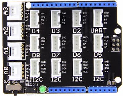
- Seeed Studio Grove Base Shield V2.0
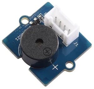
- Seeed Studio Grove - Piezo Buzzer/Active Buzzer.
Connections
- Buzzer positive terminal connected to pin PA9 (through Grove Base Shield Connector D8).
- Buzzer negative terminal connected to GND (through Grove Base Shield Connector D8).
🚨 Important Note:
I used the Grove modular system for connection ease. It is a more elegant approach and less prone to mistakes. One can directly wire the buzzer to the board pins if need be.
Software Design
📝 Note:
The code in this post is an adaptation in Rust of the buzzer example provided by Seeed Studio here.
The buzzer used is quite simple to operate. Through the buzzer-connected signal pin, various tones can be generated by the controller PWM peripheral. This occurs by changing the PWM frequency to match the needed tone. As a result, to generate a certain tune a collection of tones at a certain rate (tempo) need to be provided to the PWM peripheral. This also means that the code would need to include some data structures storing the needed information to provide to the PWM peripheral. Two data structures are needed, the first would include a mapping between notes and their associated frequencies. The second would represent a tune that includes a collection of notes each played for a certain amount of beats.
Following that information, after configuring the device, the algorithmic steps are as follows:
- From the tune array data structure obtain a note and its associated beat
- From the tones array retrieve the frequency associated with the note obtained in step 1
- Play the note for the desired duration (number of beats * tempo)
- Include half a beat of silence (0 frequency) between notes
- Go back to 1.
There are fine details in between relative to the PWM details that will be discussed in detail in the implementation.
Code Implementation
Crate Imports
In this implementation, the following crates are required:
- The
cortex_m_rtcrate for startup code and minimal runtime for Cortex-M microcontrollers. - The
panic_haltcrate to define the panicking behavior to halt on panic. - The
stm32f4xx_halcrate to import the STMicro STM32F4 series microcontrollers device hardware abstractions on top of the peripheral access API.
use cortex_m_rt::entry;
use panic_halt as _;
use stm32f4xx_hal::{
    pac::{self},
    prelude::*,
    timer::Channel,
};
Peripheral Configuration Code
GPIO Peripheral Configuration:
1️⃣ Obtain a handle for the device peripherals: In embedded Rust, as part of the singleton design pattern, we first have to take the PAC level device peripherals. This is done using the take() method. Here I create a device peripheral handler named dp as follows:
let dp = pac::Peripherals::take().unwrap();
2️⃣ Promote the PAC-level GPIO structs: In this application, I'm going to need one pin that will be generating the PWM output. The pin being used is PA9 as stated earlier and it's one of the pins that support PWM output. In fact, it can be connected internally to timer 1 or TIM1. Before I can obtain a handle for PA9 I need to promote the pac-level GPIOA struct to be able to create handles for individual pins. I do this by using the split() method as follows:
let gpioa = dp.GPIOA.split();
3️⃣ Obtain a handle and configure the PWM pin: Here PA9 needs to be configured such that it's connected to the internal circuitry of TIM1 that enables generating a PWM output. This is done using the into_alternate generic Pin type method. I will name the handle buzz and configure it as follows:
let buzz = gpioa.pa9.into_alternate();
PWM Timer Peripheral Configuration:
1️⃣ Configure the system clocks: The system clocks need to be configured as they are needed in setting up the timer peripheral. To set up the system clocks we need to first promote the RCC struct from the PAC and constrain it using the constrain() method (more detail on the constrain method here) to give use access to the cfgr struct. After that, we create a clocks handle that provides access to the configured (and frozen) system clocks. The clocks are configured to use an HSE frequency of 8MHz by applying the use_hse() method to the cfgr struct. The HSE frequency is defined by the reference manual of the Nucleo-F401RE development board. Finally, the freeze() method is applied to the cfgr struct to freeze the clock configuration. Note that freezing the clocks is a protection mechanism by the HAL to avoid the clock configuration changing during runtime. It follows that the peripherals that require clock information would only accept a frozen Clocks configuration struct.
let rcc = dp.RCC.constrain();
let clocks = rcc.cfgr.use_hse(8.MHz()).freeze();
2️⃣ Obtain a PWM handle and configure the timer: The way PWM is structured in the stm32f4xx-hal is somewhat confusing. In the STM32F401 device the TIM1 timer, has 4 channels that can each be connected to PWM output pins. In past posts when configuring peripherals like the UART, it was demonstrated how the peripheral can be configured using extension traits or the peripheral abstraction to instantiate an instance. The confusing part here is that between the extension traits and the abstractions, it seems that the different pwm abstractions do not have a method to instantiate an instance. Instead, in order to instantiate a PWM peripheral (create a handle) there are the following two options:
- Pass a tuple of
Pinhandles into one of thepwmextension traits and apply thesplitmethod to obtain a tuple of handles of typePWMChannel. - Pass a single
Pinhandle into one of thepwmextension traits to obtain aPwmtype.
Going with option 2 will consequently require that I pass the channel number into the methods I use which will be seen later. Simply put, as the stm32f4xx-hal stands right now, PWM instances can be created only by applying traits on timer peripherals. So, since I'm using only a single pin, I need only a single channel so I elected to go with the second option for my application. I created a buzz_pwm handle as follows:
let mut buzz_pwm = dp.TIM1.pwm_hz(buzz, 2000.Hz(), &clocks);
Breaking this line down, you can see I am using the pwm_hz method which has the following signature:
    fn pwm_hz<P, PINS>(
        self,
        pins: PINS,
        freq: Hertz,
        clocks: &Clocks
    ) -> PwmHz<Self, P, PINS>
    where
        PINS: Pins<Self, P>;
As can be seen, the pwm_hz method returns a PwmHz type in which I am also passing as arguments the buzz pin handle, the PWM frequency, and the frozen clocks handle. The reason that I chose is because pwm_hz among the other two available methods is that its methods are going to allow me to easier change the PWM output based on frequency values.
🚨 Important Note:
At the time of writing this post, I noticed that if going with option 1 stated earlier that returns a
PWMChannelcan prove to be quite problematic. In navigating the documentation, thePWMChannelimplementations do not include methods that allow to get and set the period of the peripheral. There is an issue that I submitted here for that.
3️⃣ Configure the PWM duty cycle: Here all I need is to generate a regular square wave, so I need a duty cycle of 50%. This is being done over two steps as follows:
let max_duty = buzz_pwm.get_max_duty();
buzz_pwm.set_duty(Channel::C2, max_duty / 2);
Analyzing the above lines, the first line applies the get_max_duty method on the buzz_pwm handle which returns a u16 value representing the maximum duty cycle. The second line applies the set_duty method that accepts two parameters, an enum of the channel that that pin is connected to and the duty cycle value. It can be determined from the device datasheet that pin PA9 is connected to channel 2 of the timer. In any case, if by mistake the programmer happens to insert the incorrect channel number, the compiler will generate an error.
🚨 Important Note:
I've found that by skipping this step (not configuring the duty cycle) the PWM output will not operate properly. I had assumed that the code would fall back to a default value but that was not the case.
Timer and Delay Peripheral Configuration:
In the algorithm, a delay will need to be introduced to control the tempo. Since I am already using TIM1 I need to leverage a different timer of which I will be using TIM2. I create a millisecond delay handle delay as follows:
let mut delay = dp.TIM2.delay_ms(&clocks);
This is it for configuration! Let's now jump into the application code.
Application Code
According to the software design description, two arrays are needed to store the tone and tune information. The first array tones, contains a collection of tuples that provide a mapping of the note letter and its corresponding frequency. The second array tune contains a collection of tuples that present the note that needs to be played and the number of beats per note. Note that the tune array contains an empty note ' ' that presents silence and does not have a corresponding mapping in the tones array.
    let tones = [
        ('c', 261.Hz()),
        ('d', 294.Hz()),
        ('e', 329.Hz()),
        ('f', 349.Hz()),
        ('g', 392.Hz()),
        ('a', 440.Hz()),
        ('b', 493.Hz()),
    ];

    let tune = [
        ('c', 1),
        ('c', 1),
        ('g', 1),
        ('g', 1),
        ('a', 1),
        ('a', 1),
        ('g', 2),
        ('f', 1),
        ('f', 1),
        ('e', 1),
        ('e', 1),
        ('d', 1),
        ('d', 1),
        ('c', 2),
        (' ', 4),
    ];
Next, before jumping into the algorithmic loop the tempo needs to be defined which will be used in the delay handle. A tempo variable is created as follows:
let tempo = 300_u32;
Next, the application loop looks as follows:
    loop {
        // 1. Obtain a note in the tune
        for note in tune {
            // 2. Retrieve the freqeuncy and beat associated with the note
            for tone in tones {
                // 2.1 Find a note match in the tones array and update frequency and beat variables accordingly
                if tone.0 == note.0 {
                    // 3. Play the note for the desired duration (beats*tempo)
                    // 3.1 Adjust period of the PWM output to match the new frequency
                    buzz_pwm.set_period(tone.1);
                    // 3.2 Enable the channel to generate desired PWM
                    buzz_pwm.enable(Channel::C2);
                    // 3.3 Keep the output on for as long as required
                    delay.delay_ms(note.1 * tempo);
                } else if note.0 == ' ' {
                    // 2.2 if ' ' tone is found disable output for one beat
                    buzz_pwm.disable(Channel::C2);
                    delay.delay_ms(tempo);
                }
            }
            // 4. Silence for half a beat between notes
            // 4.1 Disable the PWM output (silence)
            buzz_pwm.disable(Channel::C2);
            // 4.2 Keep the output off for half a beat between notes
            delay.delay_ms(tempo / 2);
            // 5. Go back to 1.
        }
    }
Let's break down the loop line by line. The line
for note in tune
iterates over the tune array obtaining a note with each iteration. Within the first loop another for loop for tone in tones is nested which iterates over the tones array. The second loop retrieves the frequency and beat associated for each note obtained from the tune array. The statement
if tone.0 == note.0
checks if there is a match for the mapping between the note and the tone. The .0 index is in reference to the first index in the tuple which is the note letter. Once a match is found, the note is played for the desired duration which equals the beats multiplied by the tempo. This is done over three steps:
First, using the set_period method in the PwmHz abstraction, the tone frequency is adjusted to match the frequency of the found tone. The frequency of the tone corresponds to index 1 o the tuple and is configured as follows:
buzz_pwm.set_period(tone.1);
Second, using the enable method the buzz_pwm channel is enabled to activate the desired PWM.
buzz_pwm.enable(Channel::C2);
In the third and final step the output is kept on for a period of beat*tempo milliseconds. Here I leverage the delay handle created earlier as follows:
delay.delay_ms(note.1 * tempo);
In the case a ' ' note is found the following lines are executed:
else if note.0 == ' ' {
           buzz_pwm.disable(Channel::C2);
           delay.delay_ms(tempo);
}
Which disables the PWM channel output for one beat.
Finally, after exiting the inner loop, half a beat of silence is introduced between notes in the outer loop tune as follows:
buzz_pwm.disable(Channel::C2);
delay.delay_ms(tempo / 2);
🚨 Important Note:
Some of the previous methods do not have a description in the documentation. However, the name of the method itself is quite intuitive to figure out what it does.
Full Application Code
Here is the full code for the implementation described in this post. You can additionally find the full project and others available on the apollolabsdev Nucleo-F401RE git repo.
#![no_std]
#![no_main]

// Imports
use cortex_m_rt::entry;
use panic_halt as _;
use stm32f4xx_hal::{
    pac::{self},
    prelude::*,
    timer::Channel,
};

#[entry]
fn main() -> ! {
    // Setup handler for device peripherals
    let dp = pac::Peripherals::take().unwrap();

    // Set up the clocks
    let rcc = dp.RCC.constrain();
    let clocks = rcc.cfgr.use_hse(8.MHz()).freeze();

    // Configure the Buzzer pin as an alternate and obtain handler.
    // I will use PA9 that connects to Grove shield connector D8
    // On the Nucleo FR401 PA9 connects to timer TIM1
    let gpioa = dp.GPIOA.split();
    let buzz = gpioa.pa9.into_alternate();
    let mut buzz_pwm = dp.TIM1.pwm_hz(buzz, 2000.Hz(), &clocks);

    // Configure the duty cycle to 50%
    // If duty not configured, PWM will not operate properly (suggest comments)
    let max_duty = buzz_pwm.get_max_duty();
    buzz_pwm.set_duty(Channel::C2, max_duty / 2);

    // Configure and create a handle for a second timer using TIM2 for delay puposes
    let mut delay = dp.TIM2.delay_ms(&clocks);

    // Define the notes and their frequencies
    let tones = [
        ('c', 261.Hz()),
        ('d', 294.Hz()),
        ('e', 329.Hz()),
        ('f', 349.Hz()),
        ('g', 392.Hz()),
        ('a', 440.Hz()),
        ('b', 493.Hz()),
    ];

    // Define the notes to be played and the beats per note
    let tune = [
        ('c', 1),
        ('c', 1),
        ('g', 1),
        ('g', 1),
        ('a', 1),
        ('a', 1),
        ('g', 2),
        ('f', 1),
        ('f', 1),
        ('e', 1),
        ('e', 1),
        ('d', 1),
        ('d', 1),
        ('c', 2),
        (' ', 4),
    ];

    // Define the tempo
    let tempo = 300_u32;

    // Application Loop
    loop {
        // 1. Obtain a note in the tune
        for note in tune {
            // 2. Retrieve the freqeuncy and beat associated with the note
            for tone in tones {
                // 2.1 Find a note match in the tones array and update frequency and beat variables accordingly
                if tone.0 == note.0 {
                    // 3. Play the note for the desired duration (beats*tempo)
                    // 3.1 Adjust period of the PWM output to match the new frequency
                    buzz_pwm.set_period(tone.1);
                    // 3.2 Enable the channel to generate desired PWM
                    buzz_pwm.enable(Channel::C2);
                    // 3.3 Keep the output on for as long as required
                    delay.delay_ms(note.1 * tempo);
                } else if note.0 == ' ' {
                    // 2.2 if ' ' tone is found disable output for one beat
                    buzz_pwm.disable(Channel::C2);
                    delay.delay_ms(tempo);
                }
            }
            // 4. Silence for half a beat between notes
            // 4.1 Disable the PWM output (silence)
            buzz_pwm.disable(Channel::C2);
            // 4.2 Keep the output off for half a beat between notes
            delay.delay_ms(tempo / 2);
            // 5. Go back to 1.
        }
    }
}
Conclusion
In this post, a buzzer application that plays a tune was created leveraging the timer peripheral PWM output for the STM32F401RE microcontroller on the Nucleo-F401RE development board. All the code was created at the HAL level using the stm32f4xx Rust HAL. Have any questions? Share your thoughts in the comments below 👇.