


Often I encounter embedded designers asking the following:
How do I determine the power consumption of the system I created?
How long will my hardware run on battery?
What type of power source should I choose?
The answers to all these questions come down to determining your system/device power budget. This means you need to calculate how much power your system needs at a minimum to function properly. In this post, I will be attempting to introduce a framework using a simple example that you can adjust to figure out your design power budget. Mind that this is not a detailed analysis, but rather a rough one that would be a good start for most systems. This framework can be expanded to whichever level of detail a designer would like. You can also access a free Google sheet I created that is based on the design described in this post by signing up for the newsletter here.
A Simple System Abstraction
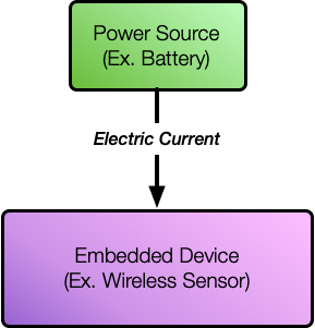
Ahead of delving into calculations, I'm going to start with a very simple abstraction. Any embedded device is typically hooked up through a single connection to a power source that has a certain voltage. The power source could be a battery, USB connection, or what have you. Additionally, the embedded device powers its internal circuitry by consuming electric current from the source. In power budgeting, the goal thus becomes calculating, on average, how much current the embedded device will consume from the power source over time.
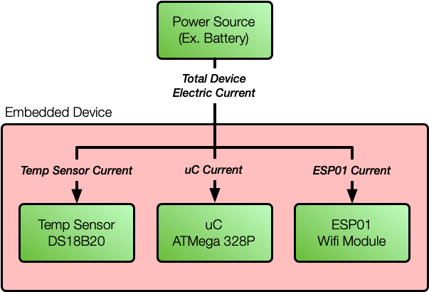
Let's expand this a bit further. So, in order to determine the total current being consumed by our device, we need to determine how much current is being consumed by the internal components. As we know, there are multiple internal components that are feeding off the main supply line. Additionally, each one of these components consumes a certain amount of current. This means that we would need to identify each component that is feeding off the supply and determine how much current each consumes. Simply adding the current consumed by each component gives us our total current consumed.
Though there's still more we need to consider. Based on our initial abstraction, a simple assumption would be that the device continuously consumes the same amount of current over time. Though this is not the case for most embedded devices as they typically have different states or modes of operation. Each mode defines what the device is doing and thus what internal circuitry is active. As such, it follows that depending on how much circuitry is active internal to the embedded device, the source current could increase or decrease. Now the question then becomes, if we have different modes of operation scenarios, how do we calculate the average current consumption? In order to do that, the designer needs to define the modes of operation and what percentage of time the device will be spending in each mode. This is best explained by an example in what follows.
A Simple System Example
We are now going to expand on our abstraction with a simple system and work through an example. We are going to consider a simple embedded IoT device that collects temperature information from a sensor and then transmits it wirelessly over WiFi. As such we need to analyze current consumption by all the components that are connected to the power source. The system has three main components (or circuits) that are feeding off the main power source:
- DS18B20 digital temperature sensor for providing temperature data (DS18B20 datasheet).
- Microchip 8-bit ATmega328P Microcontroller Device to manage the system, collect, process, and send temperature data (ATmega328P datasheet).
- ESP01 Wifi module to transmit collected data (ESP01 datasheet).
Let's also assume that our power source is a Li-ion battery that has a capacity of 600 mAh. Now that we have identified the system components we can determine our different operation scenarios.
Continous Operation Scenario
This is the simplest operating scenario to calculate and also can be considered the worst case. In this scenario, we are continuously collecting temperature data and transmitting it. This means that all components connected to the power source are active and simultaneously drawing current. This type of mode allows us to check for the worst-case power budget needed without introducing any optimizations.
In order to determine the current consumption for this mode, we need to find out how much current will each component consume while active. For this we need to refer to the datasheet of each component and we need to know the system operation voltage. Given the components we have, we will choose a 3.3V power supply. A good rule of thumb in choosing the power supply voltage is to find the lowest possible operating voltage common to all components in your system. While there might be more considerations to take into account, lower voltage means lower power consumption which typically is a central goal. Now, back to current consumption, for the ESP01 we would find that using 802.11g in transmit mode the current consumption is 170mA (Page 17 of datasheet). Additionally for the DS18B20 temperature sensor the consumption is 4mA (Page 2 of DS18B20 datasheet). Finally, for the microcontroller the current consumption is 2.4mA if we are running the device on a 4MHz Clock (Page 260 of datasheet). Now all we have to do is add all the figures up to give us the maximum current consumption as such:
$$
I_{tot} = 170\text{ mA}+2.4\text{ mA}+4\text{ mA} =176.4\text{ mA}
$$
This means that our system continuously over time is sourcing 176.4 mA from our power source. So now for our 600 mAh battery we can calculate the duration the system will operate on a single charge simply by dividing the capacity by the current. This results in the following:
$$
T_{op} = \frac{600\text{ mAh}}{176.4\text{ mA}} = 3.4 \text{ hours}
$$
This means that our system can survive for 3.4 hours before requiring a recharge or new battery. Obviously, for a simple system like the one we have, 3.4 hours on a full charge is certainly not desirable. This also means that we need a better solution and we know we could do better. One straightforward approach one can think of is to change the power supply. For example, one can use a battery with a larger capacity or switch to a continuous source from USB power. However, the issue is that it still might not be acceptable for your requirements. As such, this is when we need to resort to multi-mode operation.
Multi-Mode Operating Scenario
In a multi-mode operating scenario, we need to define multiple modes of operation that our device will cycle through. In each of the modes we will have the different components operating in different power modes leading to different current consumption per mode. Meaning, why would I indefinitely operate all my components when I am not using them all time? I could turn some off or send them to sleep and save power in the process. In doing that, ultimately the goal is to bring down on average the current consumption that is being sourced from the power supply over time. Additional to all that, now that we need to calculate an average current, a time component is also necessary. This means that we need to define for a single operation cycle switching between modes, how long are we staying in each mode.
Lets start by defining the modes for our simple system. Keep in mind that, the number of operation modes is really up to the designer and what they see fit. Since our system is a temperature measurement system, we can assume that temperature changes for our environment don't happen rapidly. This means if we take measurements every now and then we can still provide a reliable measure. For our system we are going to assume three operating modes as follows:
- Idle Mode: in this mode, all the components are in a low power mode and no activity is happening. We are going to spend 10 seconds in this mode.
- Data Collection Mode: in this mode, the device is awake and collecting data only without transmitting anything. This means that the controller is actively collecting data from the temperature sensor, making the controller and the temperature sensor both in active mode and the transmitter in sleep mode. We assume that the system will collect temperature data averaged over 5 seconds for accuracy.
- Transmission Mode: in this mode, the device is transmitting the data that was collected. As such, the ESP01 is on and in transmit mode, the controller is active also controlling the ESP, but the temperature sensor is idle. According to the ESP01 datasheet, the device needs at least 1 second to wake up and connect to the access point (AP).
Again, we have to refer to the datasheets to retrieve the current consumption values for our low power operating/sleep modes of the components. At this point, it would be good practice if we start a table as follows:
| Mode | Current Consumption | Time in Mode | Charge Consumed |
| Idle | Temp Sensor: 1uA Microcontroller: 0.6mA ESP01: 0.9mA Mode Total= 1.501mA | 10 s | 15.01 mA*s |
| Data Collection | Temp Sensor: 1.5mA Microcontroller: 2.4mA ESP01: 0.9mA Mode Total= 4.8mA | 5 s | 24 mA*s |
| Transmission | Temp Sensor: 1uA Microcontroller: 2.4mA ESP01: 170 mA Mode Total= 172.4mA | 1 s | 172.4 mA*s |
| TOTAL | - | 16 s | 211.41 mA*s |
If you notice, we added a column that captures the charge consumed in each mode which has the units mA*s. This value gives us the total current consumed over the operation time in each mode. As such if we want to obtain the current that the system is consuming on average over all modes, we simply divide the total charge consumed over the total operating time of all modes as follows:
$$
I_{avg} = \frac{211.41\text{ mA*s}}{16\text{ s}} = 13.21 \text{ mA}
$$
This means that our device consumes on average 13.21 mA during operation, this is a significant reduction from the 176 mA that we've seen earlier. So for the same battery capacity of 600mA, our total operating time now is as follows:
$$
T_{op} = \frac{600\text{ mAh}}{13.21\text{ mA}} = 45.41 \text{ hours}
$$
Again, a significant enhancement from the 3.4 hours that we've seen before in continuous operation. Though this still might not be enough in some cases. At this point, the designer can improvise even further by analyzing what is acceptable for the system. Also if you look further you would notice that the transmission mode is on 6% of the time, but accounts for 81% of the system power consumption. As such, some options for prolonging operation without recharge include:
- Increasing battery capacity.
- Reducing the overall amount of time spent in the highest power modes by increasing the lower power modes time in mode.
- Checking if the system components offer even lower power modes to reduce the current consumption of existing modes.
- Adding additional low power modes. For example, one can take multiple measurements over an hour and buffer before needing to transmit.
- Consider looking for different components that are lower in power.
- Consider gating any unused circuitry in hardware in certain modes.
Additional Considerations
Accuracy of Calculations
Note that these are rough calculations and they might do just fine in several contexts. Though keep in mind that depending on the devices you are using, there are much more details that you can go through to achieve more accurate estimates. To gain more accuracy things you need to consider include:
- Compensating for consumption in devices wake up time.
- Consumption of any additional circuitry on your board connected to your power source such as pull-up resistors.
- In-depth consumption of microcontrollers as data sheets provide more granularity if desired for taking into account current consumption of individual items such as I/O, ADC, and so on.
- If hardware is available, then do actual measurements on your hardware using an Ammeter.
Requirements
This might be a step that most designers would be inclined to skip, and mostly is implied based on what they know they want out of the system. Though it would be a good habit to develop. As you noticed, along with our design and calculations, we had to make a few assumptions. In proper system design, these assumptions are driven by requirements. This is important because the same exact system, put in a different context, might need to operate in a different manner. For example, our temperature measurement system can assume that significant temperature changes don't happen rapidly, which might be true for an outdoor environment. However, this would be totally different if instead, you are monitoring the inner temperature of an appliance like an industrial oven. This probably would mean that measurements need to happen more often than in an outdoor system.
As known, especially in embedded there are so many constraints that need to be taken into consideration. As such, in order to define the requirements you need to answer questions about your system such as follows:
- What is the environment like? What is the operating temperature? For example, if using a battery, some chemistries cannot handle high temperatures.
- Does the system have any latency restrictions?
- What is the maximum size/volume the device can occupy? Different power sources have different form factors.
- Does your device need to be portable?
- What is the maximum allowed current limit (if any)?
- How long is the system expected to survive off a single charge?
- What is the minimum acceptable sampling rate for a measurement?
- How much data is the system required to measure?
- How often does the system need to take measurements?
- Does the measurement need to be triggered by an external (wireless) source?
- What is the minimum amount of data that you need to transmit? Can you process more locally to reduce transmission times?
- What is the minimum transmission power required? lower transmit power also implies lesser transmission distance.
As you can see, the requirements provide a clearer direction and, ideally, eliminates any assumptions and guesswork. In essence, you need to make sure that when you design your system to meet the requirements at hand even if they are incomplete at the beginning. If things change, you may even add requirements later as you go and adjust your system accordingly if need be.
Conclusion
Power budgeting is an important aspect of the design of embedded systems. For example, with the prevalence of IoT applications, there will be a huge amount of edge devices that will be both wireless and battery-operated. This means more care should be taken when designing edge devices to prolong their life under a single charge. As such, embedded designers should become more acquainted with power budgeting and determining how to get the longest possible operation time from their system. This post hopefully gave enough insight to get the interested acquainted with the basic framework to achieve that. Feel free to ask your questions and provide your comments below. Also, don't forget you can access a free Google sheet I created that is based on the design described in this blog post by signing up for the newsletter here.