


This blog post is the third one of a multi-part series of posts where I explore various peripherals in the ESP32C3 using embedded Rust at the HAL level. Please be aware that certain concepts in newer posts could depend on concepts in prior posts.
Prior posts include (in order of publishing):
ESP32 Embedded Rust at the HAL: GPIO Button Controlled Blinking
ESP32 Embedded Rust at the HAL: Button-Controlled Blinking by Timer Polling
Introduction
Setting up UART serial communication is useful for any type of device-to-device (point-to-point) communication. One of the common past use cases for UART was in development to print output to a PC. However, for that particular use case, nowadays some microcontrollers have advanced debug features like instruction trace macrocell (aka ITM) that don't leverage the device's own peripheral resources. Obviously, this does not make UART obsolete, as it has other use cases and some controllers don't support advanced debug to start with. In this post, I will be configuring and setting up UART communication with a PC terminal for the ESP32C3. I will be leveraging the GPIO button-controlled blinking project from a previous post to print to the console how many times the button has been pressed. Additionally, I will not be using interrupts and the example will be set up as a simplex system that transmits in one direction only (towards the PC).
📚 Knowledge Pre-requisites
To understand the content of this post, you need the following:
Basic knowledge of coding in Rust.
Familiarity with the basic template for creating embedded applications in Rust.
Familiarity with UART communication basics.
💾 Software Setup
All the code presented in this post is available on the apollolabs ESP32C3 git repo. Note that if the code on the git repo is slightly different then it means that it was modified to enhance the code quality or accommodate any HAL/Rust updates.
Additionally, the full project (code and simulation) is available on Wokwi here.
In addition to the above, if you're using real hardware, you would need to install some sort of serial communication terminal on your host PC. Some recommendations include:
For Windows:
For Mac and Linux:
Some installation instructions for the different operating systems are available in the Discovery Book.
If you are using Wokwi, then the serial terminal is integrated in the simulation window.
🛠 Hardware Setup
Materials
-
Any color LED
Current limiting resistor
Pushbutton
🔌 Connections
📝 Note
All connection details are also shown in the Wokwi example.
Connections include the following:
The LED anode through a resistor to pin 4 of the devkit. This pin will be used as an output. The cathode will be connected to ground.
One end of a button to pin 0 of the devkit This pin will be used as an input. The other end of the switch will be connected to ground.
👨🎨 Software Design
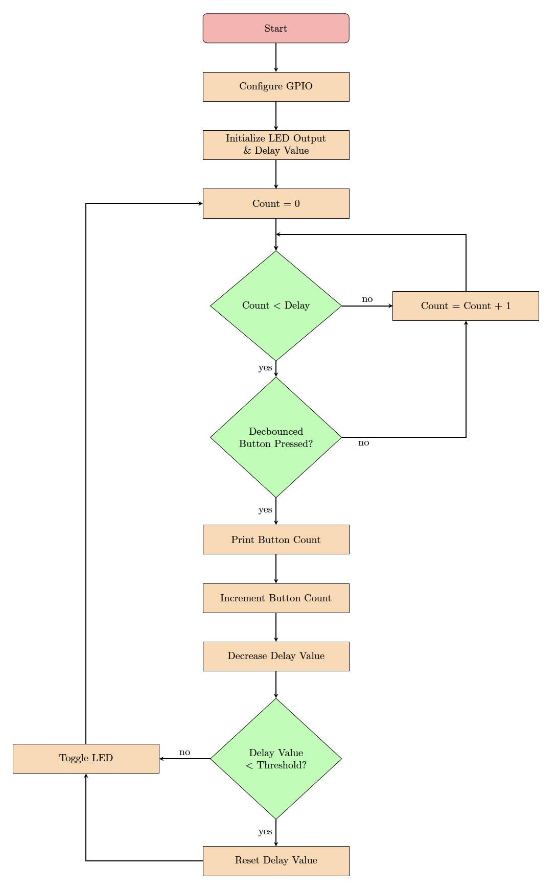
The application in this post adopts the same algorithmic approach as my previous post. Here, however, I will be adding two things:
I will be leveraging the debouncr crate (yes, that's how the crate name is spelled 😀) to eliminate the effect of button debouncing.
I will be sending/printing a value that tracks the number of times the button is pressed to the PC terminal.
The updated flow diagram would look as follows:
Let's now jump into implementing this algorithm.
👨💻 Code Implementation
📥 Crate Imports
In this implementation, three crates are required as follows:
The
esp_backtracecrate to define the panicking behavior.The
esp32c3_halcrate to import the ESP32C3 device hardware abstractions.The
debouncrcrate to debounce the button press.The
core::fmt::Writecrate will allow us to use thewriteln!macro for easy printing.
use esp32c3_hal::{clock::ClockControl, pac::Peripherals, prelude::*, timer::TimerGroup, Rtc, Delay, IO};
use esp_backtrace as _;
use debouncr::{debounce_3, Edge};
use core::fmt::Write;
📝 Note
Each of the crate imports needs to have a corresponding dependency in the Cargo.toml file.
Earlier versions of the
esp32c3_halrequired theriscv_rtcrate to be imported for startup code supporting the#[entry]attribute macro. Starting version0.7.0, an#[entry]attribute has been integrated into theesp32c3_hal. This means that an independentriscv_rtimport is not no longer required to support the#[entry]attribute.
🎛 Peripheral Configuration Code
Ahead of our application code, peripherals are configured through the following steps:
1️⃣ Obtain a handle for the device peripherals: In embedded Rust, as part of the singleton design pattern, we first have to take the PAC level device peripherals. This is done using the take() method. Here I create a device peripheral handler named dp as follows:
let peripherals = Peripherals::take();
📝 Note
This is another difference you might note relative to earlier versions of the
esp32c3_hal. In earlier implementationsPeripheralswas imported from thepacmodule, now its imported fromperipheralsinstead. While both use thetakemethod, notice that in the more recent implementation, it does not return aResultso there's no need tounwrap.
2️⃣ Disable the Watchdogs: Just like earlier posts, the ESP32C3 has watchdogs enabled by default and they need to be disabled. If they are not disabled then the device would keep on resetting. To avoid this issue, the following code needs to be included:
let system = peripherals.SYSTEM.split();
let clocks = ClockControl::boot_defaults(system.clock_control).freeze();

// Instantiate and Create Handles for the RTC and TIMG watchdog timers
let mut rtc = Rtc::new(peripherals.RTC_CNTL);
let timer_group0 = TimerGroup::new(peripherals.TIMG0, &clocks);
let mut wdt0 = timer_group0.wdt;
let timer_group1 = TimerGroup::new(peripherals.TIMG1, &clocks);
let mut wdt1 = timer_group1.wdt;
3️⃣ Instantiate and Create Handle for IO: We need to configure the LED pin as a push-pull output and obtain a handler for the pin so that we can control it. We also need to obtain a handle for the button input pin. Before we can obtain any handles for the LED and the button we need to create an IO struct instance. The IO struct instance provides a HAL-designed struct that gives us access to all gpio pins thus enabling us to create handles for individual pins. This is similar to the concept of a split method used in other HALs (more detail here). We do this by calling the new() instance method on the IO struct as follows:
let io = IO::new(peripherals.GPIO, peripherals.IO_MUX);
4️⃣ Obtain a handle for the LED and configure it to output: As earlier stated, the LED is connected to pin 4 (gpio4). As such, we need to create a handle for the LED pin that has gpio4 configured to a push-pull output using the into_push_pull_output() method. We will name the handle led and configure it as follows:
let mut led = io.pins.gpio4.into_push_pull_output();
This HAL documentation page has the full list of methods that the GpioPin type supports.
5️⃣ Obtain a handle and configure the input button: The push button is connected to pin 0 (gpio0) as stated earlier. Additionally, in the pressed state, the button pulls to ground. Also, for the button unpressed state, a pull-up resistor needs to be included so the pin goes high. An internal pull-up can be configured for the pin using the into_pull_up_input() method as follows:
let button = io.pins.gpio0.into_pull_up_input();
Note that as opposed to the LED output, the button handle here does not need to be mutable since we will only be reading it.
6️⃣ Obtain a handle and configure UART channel: On the ESP32C3 there are RX and TX pins that are configured by default to connect to UART0. As such, there is no need to configure any new pins for UART operation. As a result, to instantiate UART, in the documentation, there exists a new method to instantiate a UART channel and has the following signature:
pub fn new(uart: impl Peripheral<P = T> + 'd) -> Uart<'d, T>
This method instantiates UART with a default configuration. The default configuration can be found in the source code and has the following parameters:
impl Default for Config {
    fn default() -> Config {
        Config {
            baudrate: 115_200,
            data_bits: DataBits::DataBits8,
            parity: Parity::ParityNone,
            stop_bits: StopBits::STOP1,
        }
    }
}
Since we need to instantiate a UART instance for UART0 this will result in the following code:
let mut uart0 = Uart::new(peripherals.UART0);
🚨 Important Notes:
To figure out what the default configuration entails, I had to go into the source code and find the
Defaulttrait implementation. Unfortunately, the HAL documentation itself does not make it easily obvious what the default configuration is.If one wishes to configure UART with different parameters, there exists a
new_with_configfunction that can be called instead when creating a UART instance.
💰 Tip:
In Wokwi, there is a useful approach to determine if the pins are configured correctly. After hitting the play button, hit pause while the simulation is running. The active pin functions will be printed beside each pin.
📱 Application Code
Following the design described earlier, I first need to initialize a delay variable del_var and initialize the output of the LED. del_var needs to be mutable as it will be modified by the delay loop. I also choose to set the initial led output level to low by default. Using the same Pin methods mentioned earlier, there is a set_low() method that I use to achieve that.
// Create and initialize a delay variable to manage delay loop
let mut del_var = 10_0000_u32;

// Initialize LED to on or off
led.set_low().unwrap();
I also want to initialize a variable value that I want to use to track how many times the button has been pressed:
let mut value: u8 = 0;
Afterward, I have one small thing remaining. I mentioned that I will be using the debouncr crate to debounce button presses. This means I need to create some sort of handler to utilize the crate methods. In the crate documentation, to instantiate, I first need to determine how many states need to be detected. I chose 16.
let mut debouncer = debounce_16(false);
The reason I initialized debouncer to false is that the documentation mentioned that I have to do that if the button is active low.
🚨 Important Notes:
To choose the debounce states, I experimented and found that, on hardware, 3 states were sufficient to eliminate the effect. However, in Wokwi I didnt see a result consistent with hardware. Although I put in the maximum number of states allowed, the bouncing effect was reduced, though not eliminated.
Next inside the program loop, I first start by calling a delay function where inside of it I check if the button is pressed. After the delay completes, I toggle led using the toggle() method, again part of the methods available for the Pin type. This is the complete application loop:
loop {
    for _i in 1..del_var {
        if debouncer.update(button.is_low().unwrap()) == Some(Edge::Falling) {
            writeln!(tx, "Button Press {:02}\r", value).unwrap();
            value = value.wrapping_add(1);
            del_var = del_var - 2_5000_u32;
            if del_var < 2_5000_u32 {
                del_var = 10_0000_u32;
            }
            break;
        }
    }
    led.toggle();
}
The general structure is exactly the same as the application loop in the regular polled button-controlled blinking application. The outer for loop is the one that keeps track of the delay through del_var. A difference here is the if statement condition. For the condition, I am leveraging the update method from the debouncr crate. When polling the pin, the update method is repeatedly called. The update method returns an Option enum that keeps providing a None when no press is detected. However, if a (debounced) press is detected, the update method returns either a Some(Edge::Falling) or Some(Edge::Rising). Since the ESP32C3 has an active-low button, a press is detected with a falling edge and a Some(Edge::Falling) is returned on a successful debounce.
Once the button detect is completed, I use the writeln! macro provided by core::fmt::Write that I imported earlier. The usage is exactly the same as the formatted print using println! in Rust with a couple of small exceptions. Examining the statement,
writeln!(uart0, "Button Press {:02}\r", value).unwrap();
If you have noticed, writeln! takes three parameters and in the first parameter of writeln!, I am passing the uart0 handler as an argument. For writeln! to work, uart0 has to have the write_fmt function defined for the Write trait. Additionally, the writeln! macro needs to be unwrapped since it returns a Result. The third parameter of writeln! also contains the value variable initialized earlier that is being incremented by the following line as follows:
value = value.wrapping_add(1);
The wrapping_add method, as the name implies performs a wrapping add on value adding 1 every time the method is called and wraps around if needed. The remaining code takes care of decreasing the value of del_var to reduce the delay and make sure that it does not drop below zero. Finally, outside of the delay loop the led is toggled using the Pin toggle method.
💰 Tip:
In order to do console printing using the ESP, an alternative approach is to use the esp-println crate. esp-println is more portable where it provides implmenentations of
print!,println!anddbg!for various Espressif devices.
📱 Full Application Code
Here is the full code for the implementation described in this post. You can additionally find the full project and others available on the apollolabs ESP32C3 git repo. Also the Wokwi project can be accessed here.
#![no_std]
#![no_main]

use core::fmt::Write; // allows use to use the WriteLn! macro for easy printing
use debouncr::{debounce_16, Edge};
use esp32c3_hal::{
    clock::ClockControl, peripherals::Peripherals, prelude::*, timer::TimerGroup, uart::Uart, Rtc,
    IO,
};
use esp_backtrace as _;

#[entry]
fn main() -> ! {
    // Take Peripherals, Initialize Clocks, and Create a Handle for Each
    let peripherals = Peripherals::take();
    let system = peripherals.SYSTEM.split();
    let clocks = ClockControl::boot_defaults(system.clock_control).freeze();

    // Instantiate and Create Handles for the RTC and TIMG watchdog timers
    let mut rtc = Rtc::new(peripherals.RTC_CNTL);
    let timer_group0 = TimerGroup::new(peripherals.TIMG0, &clocks);
    let mut wdt0 = timer_group0.wdt;
    let timer_group1 = TimerGroup::new(peripherals.TIMG1, &clocks);
    let mut wdt1 = timer_group1.wdt;

    // Disable the RTC and TIMG watchdog timers
    rtc.swd.disable();
    rtc.rwdt.disable();
    wdt0.disable();
    wdt1.disable();

    // Instantiate and Create Handle for IO
    let io = IO::new(peripherals.GPIO, peripherals.IO_MUX);

    // Instantiate and Create Handle for LED output & Button Input
    let mut led = io.pins.gpio4.into_push_pull_output();
    let button = io.pins.gpio0.into_pull_up_input();

    // Initialize LED to on or off
    led.set_low().unwrap();

    // Create UART instance with default config
    let mut uart0 = Uart::new(peripherals.UART0);

    // Initialize debouncer to false because button is active low
    let mut debouncer = debounce_16(false);

    // Create and initialize a delay variable to manage delay loop
    let mut del_var = 10_0000_u32;

    // Variable to keep track of how many button presses occured
    let mut value: u8 = 0;

    // Application Loop
    loop {
        // Enter Delay Loop
        for _i in 1..del_var {
            // Keep checking if button got pressed
            if debouncer.update(button.is_low().unwrap()) == Some(Edge::Falling) {
                // If button is pressed print to derial and decrease the delay value
                writeln!(uart0, "Button Press {:02}\r", value).unwrap();
                // Increment value keeping track of button presses
                value = value.wrapping_add(1);
                // Decrement the amount of delay
                del_var = del_var - 2_5000_u32;
                // If updated delay value drops below threshold then reset it back to starting value
                if del_var < 2_5000_u32 {
                    del_var = 10_0000_u32;
                }
                // Exit delay loop since button was pressed
                break;
            }
        }
        led.toggle().unwrap();
    }
}
🔬 Further Experimentation/Ideas
If you have access to real hardware, try configuring UART with different parameters.
Implement UART with transmit and receive functionality.
Conclusion
In this post, an LED control application was created leveraging the GPIO and UART peripherals for the ESP32C3. The UART peripheral sends to a host PC a status update every time a GPIO button is pressed. All code was based on polling (without interrupts). All code was created at the HAL level using the esp32c3-hal.Have any questions? Share your thoughts in the comments below 👇