


This blog post is the fifth of a multi-part series of posts where I explore various peripherals in the ESP32C3 using embedded Rust at the HAL level. Please be aware that certain concepts in newer posts could depend on concepts in prior posts.
Prior posts include (in order of publishing):
ESP32 Embedded Rust at the HAL: GPIO Button Controlled Blinking
ESP32 Embedded Rust at the HAL: Button-Controlled Blinking by Timer Polling
Introduction
In this post, I will be configuring and setting up ESP32C3 timer to read an ultrasonic sensor output and measure obstacle distance. A distance measurement will be continuously collected and sent to a PC terminal. I will be leveraging the esp-println crate to print console output.
🚨 Important Note:
For the purpose of this post, ideally I would have wanted to leverage a timer peripheral input capture mode. I came to discover later that input capture is yet not supported for the esp32c3-hal. As a result, I resorted to a different approach that achieves the same thing but is considered less efficient.
Knowledge Pre-requisites
To understand the content of this post, you need the following:
Basic knowledge of coding in Rust.
Familiarity with the basic template for creating embedded applications in Rust.
Familiarity with working principles of Ultrasonic sensors. This page is a good resource.
💾 Software Setup
All the code presented in this post is available on the apollolabs ESP32C3 git repo. Note that if the code on the git repo is slightly different then it means that it was modified to enhance the code quality or accommodate any HAL/Rust updates.
Additionally, the full project (code and simulation) is available on Wokwi here.
In addition to the above, you would need to install some sort of serial communication terminal on your host PC. Some recommendations include:
For Windows:
For Mac and Linux:
Some installation instructions for the different operating systems are available in the Discovery Book.
🛠 Hardware Setup
Materials
-
An HC-SR04 Ultrasonic Sensor.
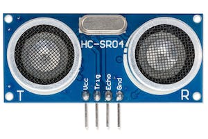
🔌 Connections
ESP32C3 GPIO0 to
A 2kOhm Resistor that's connected to Ground on the other end
A 1kOhm Resistor that's connected to the HC-SR04 echo pin on the other end
HC-SR04 trigger pin connected to ESP32C3 GPIO1
HC-SR04 Vcc pin connected to ESP32C3 5V
HC-SR04 Gnd pin connected to ESP32C3 Gnd
👨🎨 Software Design
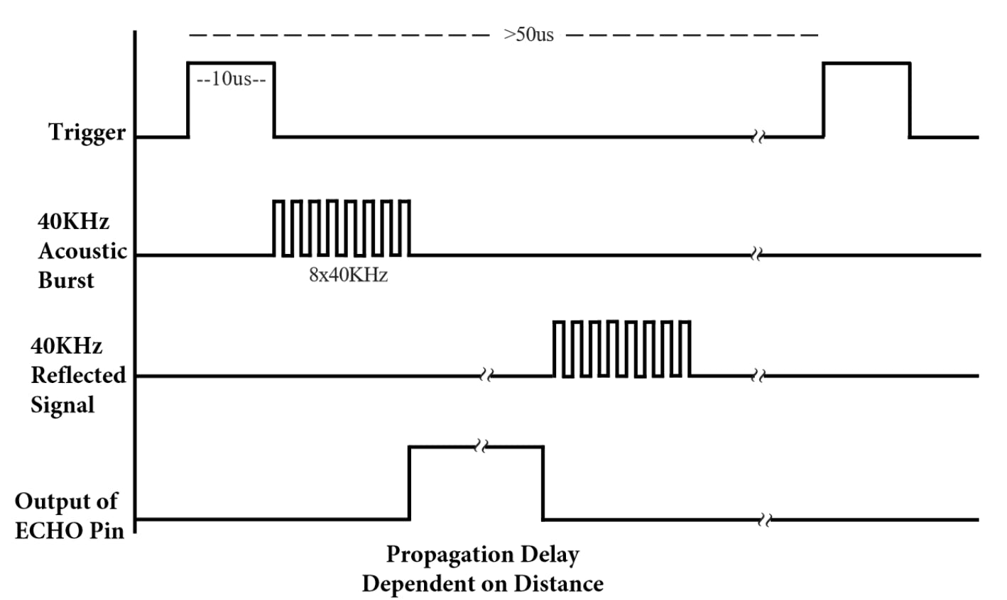
The ultrasonic sensor used is a two-pin interface sensor. The trigger pin, operating as an input, should be triggered first by a pulse that is at least 10us wide. This would cause the sensor to emit a series of ultrasonic pulses that it measures the propagation delay of. After that, the echo pin, operating as an output, provides a pulse width proportional to the distance of the obstacle away from the sensor.
The obstacle distance is calculated as:
$$d_{\text{cm}}= \frac{P_{\text{echo}}}{29*2}$$
where dcm is the obstacle distance in centimeters and Pecho is the echo pulse width in microseconds.
The algorithm is quite straightforward in this case. After configuring the device, the algorithmic steps are as follows:
Set trigger output pin to low for 5 us to get a clean low pulse
Generate 10us pulse on trigger output pin
Keep polling echo input until it goes high
Once echo input goes high kick-off counter/timer
Keep polling echo input until it goes low
Capture pulse duration measurement from counter/timer
Calculate the distance and print the result
Go back to 1
👨💻 Code Implementation
📥 Crate Imports
In this implementation, the following crates are required:
The
esp32c3_halcrate to import the ESP32C3 device hardware abstractions.The
esp_backtracecrate to define the panicking behavior.The
esp_printlncrate to provideprintln!implementation.
use esp32c3_hal::{
    clock::ClockControl, peripherals::Peripherals, prelude::*, systimer::SystemTimer,
    timer::TimerGroup, Delay, Rtc, IO,
};
use esp_backtrace as _;
use esp_println::println;
🎛 Initialization (Configuration) Code
⌨️ GPIO Peripheral Configuration:
1️⃣ Obtain a handle for the device peripherals: In embedded Rust, as part of the singleton design pattern, we first have to take the PAC-level device peripherals. This is done using the take() method. Here I create a device peripheral handler named dp as follows:
let peripherals = Peripherals::take();
2️⃣ Disable the Watchdogs: Just like earlier posts, the ESP32C3 has watchdogs enabled by default and they need to be disabled. If they are not disabled then the device would keep on resetting. To avoid this issue, the following code needs to be included:
let system = peripherals.SYSTEM.split();
let clocks = ClockControl::boot_defaults(system.clock_control).freeze();

// Instantiate and Create Handles for the RTC and TIMG watchdog timers
let mut rtc = Rtc::new(peripherals.RTC_CNTL);
let timer_group0 = TimerGroup::new(peripherals.TIMG0, &clocks);
let mut wdt0 = timer_group0.wdt;
let timer_group1 = TimerGroup::new(peripherals.TIMG1, &clocks);
let mut wdt1 = timer_group1.wdt;
3️⃣ Instantiate and Create Handle for IO: We need to configure the LED pin as a push-pull output and obtain a handler for the pin so that we can control it. We also need to obtain a handle for the button input pin. Before we can obtain any handles for the LED and the button we need to create an IO struct instance. The IO struct instance provides a HAL-designed struct that gives us access to all gpio pins thus enabling us to create handles for individual pins. This is similar to the concept of a split method used in other HALs (more detail here). We do this by calling the new() instance method on the IO struct as follows:
let io = IO::new(peripherals.GPIO, peripherals.IO_MUX);
4️⃣ Obtain Handle and Configure GPIO pins: The echo and trigger pins need to be configured as input and output, respectively. The trigger pin is configured as a push pull output and given the handle trig and the echo pin is configured as a floating input and given the handle echo:
let mut trig = io.pins.gpio1.into_push_pull_output();
let echo = io.pins.gpio0.into_floating_input();
5️⃣ Configure a Delay: in the algorithm, a delay must be introduced to control the trigger pulse width. Using the Delay struct provided by the HAL, a delay handle can be simply created as follows:
let mut delay = Delay::new(&clocks);
This is it for configuration! Let's now jump into the application code.
Application Code
Following the design described earlier, I first need to set the trig pin output to low for 5 us to get a clean low pulse.
trig.set_low().unwrap();
delay.delay_us(5_u32);
Steps 2 and 3 in the algorithm require that I set the trig pin output to high for 10us and then and then back to low again. This can be done exactly in the same manner as the previous step as follows:
trig.set_high().unwrap();
delay.delay_us(10_u32);
trig.set_low().unwrap();
Next I need to keep polling the echo pin until it goes high marking the start of the echo pulse. This is done as follows:
while !echo.is_high().unwrap() {}
Using the while loop and the is_high Pin method, the code is sticking around the same line until the echo pin input goes high.
Afterward a timer needs to be kicked off. Looking around the esp32c3-hal documentation, the only timer I could find with interfaces allowing me to capture its count value is the SystemTimer . SystemTimer is a free-running system timer that has a now method that captures the current count. The SystemTimer runs off a 16 MHz clock and does not need to be configured so it is available from the get-go. As such, the SystemTimer count is captured at the start of the echo pulse and bound to the echo_start variable:
let echo_start = SystemTimer::now();
Now that the timer is kicked off, the next step requires that we keep polling the echo pin input until it goes low. This is done exactly as before but rather using the is_low method instead as follows:
while !echo.is_low().unwrap() {}
Once the echo pin goes low, the timer count marking the end of the pulse needs to be collected as follows:
let echo_end = SystemTimer::now();
Then the pulse duration measurement needs to be calculated:
let echo_dur = echo_end.wrapping_sub(echo_start);
Remember that this value is still in counts, not microseconds. Now that the pulse duration is available, a distance can be calculated. Using the earlier presented formula, the distance in centimeters is calculated using the following code:
let distance_cm = echo_dur / 16 / 58;
Note the divide by 16 factor which is added to convert the counts to microseconds the timer clock is 16MHz.
Finally, the result is sent to the console output using the println! macro:
println!("Distance {} cm\r", distance_cm);
📱 Full Application Code
Here is the full code for the implementation described in this post. You can additionally find the full project and others available on the apollolabs ESP32C3 git repo. Also the Wokwi project can be accessed here.
#![no_std]
#![no_main]

use esp32c3_hal::{
    clock::ClockControl, peripherals::Peripherals, prelude::*, systimer::SystemTimer,
    timer::TimerGroup, Delay, Rtc, IO,
};
use esp_backtrace as _;
use esp_println::println;

#[entry]
fn main() -> ! {
    // Take Peripherals, Initialize Clocks, and Create a Handle for Each
    let peripherals = Peripherals::take();
    let system = peripherals.SYSTEM.split();
    let clocks = ClockControl::boot_defaults(system.clock_control).freeze();

    // Instantiate and Create Handles for the RTC and TIMG watchdog timers
    let mut rtc = Rtc::new(peripherals.RTC_CNTL);
    let timer_group0 = TimerGroup::new(peripherals.TIMG0, &clocks);
    let mut wdt0 = timer_group0.wdt;
    let timer_group1 = TimerGroup::new(peripherals.TIMG1, &clocks);
    let mut wdt1 = timer_group1.wdt;

    // Disable the RTC and TIMG watchdog timers
    rtc.swd.disable();
    rtc.rwdt.disable();
    wdt0.disable();
    wdt1.disable();

    // Instantiate and Create Handle for IO
    let io = IO::new(peripherals.GPIO, peripherals.IO_MUX);

    // Instantiate and Create Handle for trigger output & echo input
    let mut trig = io.pins.gpio1.into_push_pull_output();
    let echo = io.pins.gpio0.into_floating_input();

    let mut delay = Delay::new(&clocks);

    // Application Loop
    loop {
        // 1) Set pin ouput to low for 5 us to get clean low pulse
        trig.set_low().unwrap();
        delay.delay_us(5_u32);

        // 2) Set pin output to high (trigger) for 10us
        trig.set_high().unwrap();
        delay.delay_us(10_u32);
        trig.set_low().unwrap();

        // Wait until pin goes high
        while !echo.is_high().unwrap() {}

        // Kick off timer measurement
        let echo_start = SystemTimer::now();

        // Wait until pin goes low
        while !echo.is_low().unwrap() {}

        // Collect current timer count
        let echo_end = SystemTimer::now();

        // Calculate the elapsed timer count
        let echo_dur = echo_end.wrapping_sub(echo_start);

        // Calculate the distance in cms using formula in datasheet
        let distance_cm = echo_dur / 16 / 58;

        // Print the distance output
        println!("Distance {} cm\r", distance_cm);
    }
}
Conclusion
In this post, an ultrasonic distance measurement application was created leveraging the GPIO and Timer peripherals for the ESP32C3. The resulting measurement is also sent over to a host PC console using the esp-println crate. All code was based on polling (without interrupts). Additionally, all code was created at the HAL level using the esp32c3-hal. Have any questions? Share your thoughts in the comments below 👇.