


This blog post is the seventh of a multi-part series of posts where I explore various peripherals in the ESP32C3 using embedded Rust at the HAL level. Please be aware that certain concepts in newer posts could depend on concepts in prior posts.
Prior posts include (in order of publishing):
ESP32 Embedded Rust at the HAL: GPIO Button Controlled Blinking
ESP32 Embedded Rust at the HAL: Button-Controlled Blinking by Timer Polling
ESP32 Embedded Rust at the HAL: Timer Ultrasonic Distance Measurement
ESP32 Embedded Rust at the HAL: Analog Temperature Sensing using the ADC
Introduction
Dealing with interrupts on its own from an embedded microcontroller perspective is more complex than polled code. As if that weren't enough, I would say the use of Rust adds another level of complexity. This is understandable because interrupts are not safe by definition since they introduce race conditions. As a result, Rust being Rust, adds abstractions to make interrupt operations safe and prevent these race conditions. These additional abstractions might not be easy to digest for a beginner. Still, the good news is that there are alternatives out there to make using Rust with interrupts smoother. This includes the Real-Time Interrupt-driven Concurrency (RTIC) framework and the embassy framework.
In this post, I will be refactoring the GPIO button-controlled blinking application I created before and transforming it to use interrupts. I will be sticking strictly to the HAL. Along the way, I will try my best to explain the elements introduced by Rust.
📚 Knowledge Pre-requisites
To understand the content of this post, you need the following:
Basic knowledge of coding in Rust.
Familiarity with the basic template for creating embedded applications in Rust.
Familiarity with interrupts in embedded processors.
💾 Software Setup
All the code presented in this post is available on the apollolabs ESP32C3 git repo. Note that if the code on the git repo is slightly different then it means that it was modified to enhance the code quality or accommodate any HAL/Rust updates.
Additionally, the full project (code and simulation) is available on Wokwi here.
🛠 Hardware Setup
Materials
Any color LED
Current limiting resistor
Pushbutton
🔌 Connections
Connections include the following:
The LED anode through a resistor to pin 4 of the devkit. This pin will be used as an output. The cathode will be connected to ground.
One end of a button to pin 0 of the devkit This pin will be used as an input. The other end of the switch will be connected to ground.
👨🎨 Software Design
In the application developed in this post, I want to cycle through several LED blinking frequencies based on a button press. Meaning, that every time I press the on-board button, I want to see the LED turning on and off at a different rate. In this section, I will focus on the design of the application algorithm itself rather than the configuration aspects. For algorithm design purposes, I will assume that interrupts are configured already. I will be detailing the configuration steps in the implementation section.
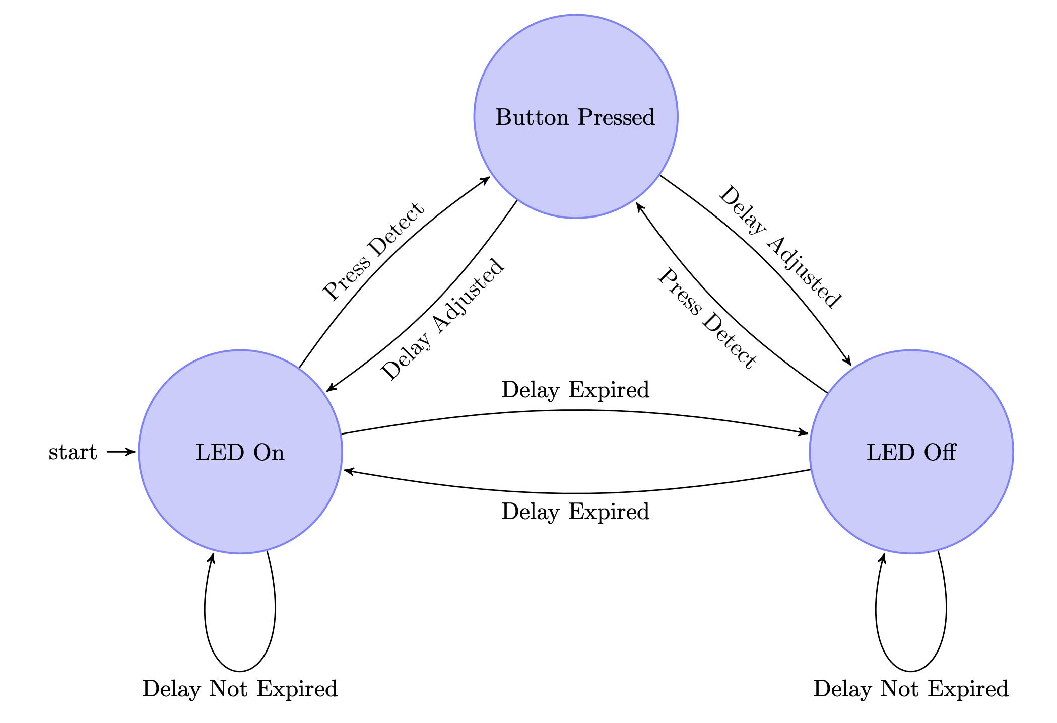
I've decided it would be best to represent the algorithm using a state machine. Here's one possible approach:
📝 Note
Although I use state machine representation. I will not be encoding any states in the code. Additionally, the representation assumes that configuration is already completed.
Let's analyze what is happening here. The application will start in a state where the LED is turned on. In this state, a timer would also be started. While in the "LED on" state two events could happen to make the system transition to another state; either a button press or a timer delay expiration. If the delay expires the application would transition to an "LED off" state that turns off the LED and resets the delay timer. On the other hand, if a button press is detected the application would transition to a "Button Pressed" state. The "Button Pressed" state would in turn adjust the amount of timer delay and then return to the state it transitioned from. The "LED off" state has exactly the same transition conditions as the "LED on" state.
In essence, interrupts are software routines that are triggered by hardware events. As such, this application can be programmed to run entirely on interrupts. This means that both hardware events causing transitions (button press and timer expiry) can be configured with interrupts. However, I won't be doing that, instead I will configure the application to use GPIO interrupts only for the button press.
Let's now jump into implementing this algorithm.
👨💻 Code Implementation
Before jumping in, I'd like to provide some context on what needs to be done for configuring interrupts in hardware and software. The hardware part is more or less the same across controllers that use a certain architecture. For embedded controllers typically the following steps need to be done to configure interrupts:
Configure and enable local interrupt behavior.
Enable interrupts at the peripheral/device level.
Enable global interrupts at the processor level.
After that, one would need to define an Interrupt Service Routine (ISR) in the application code. As one would expect, the ISR contains the code executed in response to a specific interrupt event. Additionally, inside the ISR, it is typical that one would use values that are shared with the main routine. Also in the ISR, one would have to clear the hardware pending interrupt flag to allow consecutive interrupts to happen. This is a bit of a challenge in Rust for two reasons; First, to clear the pending flag one would need to access the peripheral through its handle. This is an issue because if you recall, Rust follows a singleton pattern and we cannot have more than one reference to a peripheral. Second, in Rust, global mutable variables, rightly so, are considered unsafe to read or write. This is because without taking special care, a race condition might be triggered. To solve both challenges, in Rust, global mutable data and peripherals need to be wrapped in safe abstractions that allow them to be shared between the ISR and the main thread. Enough explanations, lets move on to the actual code.
📥 Crate Imports
In this implementation the crates required are as follows:
The
corecrate to import theCellandRefCellpointer constructs.The
critical_sectioncrate to import theMutexconstruct.The
esp32c3_halcrate to import the ESP32C3 device hardware abstractions.The
esp_backtracecrate to define the panicking behavior.The
esp_printlncrate to provideprintln!implementation.
use core::cell::{Cell, RefCell};
use critical_section::Mutex;
use esp32c3_hal::{
    clock::ClockControl,
    esp_riscv_rt::entry,
    gpio::{Event, Gpio0, Input, PullUp},
    // gpio_types::{Event, Input, Pin, PullDown},
    interrupt,
    // pac::{Interrupt, Peripherals},
    prelude::*,
    soc::peripherals::{Interrupt, Peripherals},
    timer::TimerGroup,
    Delay,
    Rtc,
    IO,
};
use esp_backtrace as _;
use esp_println::println;
🌍 Global Variables
In the application at hand, I'm choosing to enable interrupts for the GPIO peripheral to detect a button press. As such, I would need to create a global shared variable to access the GPIO peripheral (remember the singleton pattern). This is because I would need to subsequently disable the interrupt pending flag in the ISR. In particular, I will be using Gpio0 as the GPIO input pin that I want to enable interrupts for. For that I create a static global variable called G_BUTTON wrapping Gpio0 in a safe abstraction as follows:
static G_BUTTON: Mutex<RefCell<Option<Gpio0<Input<PullUp>>>>> = Mutex::new(RefCell::new(None));
So here the peripheral is wrapped in an Option that is wrapped in a RefCell, that is wrapped in a Mutex. The Mutex makes sure that the peripheral can be safely shared among threads. This means it would require that we use a critical section every time we want to access the peripheral. The RefCell is used to be able to obtain a mutable reference to the peripheral. Finally, the Option is used to allow for lazy initialization as one would not be able to initialize the variable until later (after I configure the GPIO button).
Next, I create a global variable G_DELAYMS to carry the delay value that I'm going to pass around for determining the blinking delay. This is a variable that will be used by the main thread and modified by the ISR. I initialize the delay to 2000_u32 which will correspond to two seconds.
static G_DELAYMS: Mutex<Cell<u32>> = Mutex::new(Cell::new(2000_u32));
Note two differences here from the peripheral global variable. First, I am not using an Option since I am directly initializing with a value. Second, I am using a Cell rather than a RefCell. This is because Cell only permits taking a copy of the current value or replacing it, not taking a reference which is not needed with a u32.
📝 Notes:
1️⃣ These global variables can be viewed as entities that exist in a global context where access is obtained at runtime by the thread that needs them. This is why
RefCellis needed. Compared to aBox,RefCellallows for checking during runtime that only one mutable reference exists to a variable. ABoxmakes sure statically at compile time that only one mutable reference exists. ObviouslyBoxcannot be used with interrupts as multiple threads would require mutable access during runtime.2️⃣ I would strongly recommend referring to Chapter 6 of the Embedded Rust Book for more detail on this topic.
🎛 Peripheral Configuration Code
1️⃣ Obtain a handle for the device peripherals: In embedded Rust, as part of the singleton design pattern, we first have to take the PAC level device peripherals. This is done using the take() method. Here I create a device peripheral handler named dp as follows:
let peripherals = Peripherals::take();
2️⃣ Disable the Watchdogs: The ESP32C3 has watchdogs enabled by default and they need to be disabled. If they are not disabled then the device would keep on resetting. I'm not going to go into much detail, however, watchdogs require the application software to periodically "kick" them to avoid resets. This is out of the scope of this example, though to avoid this issue, the following code needs to be included:
let mut system = peripherals.SYSTEM.split();
let clocks = ClockControl::boot_defaults(system.clock_control).freeze();

let mut rtc = Rtc::new(peripherals.RTC_CNTL);
let timer_group0 = TimerGroup::new(
        peripherals.TIMG0,
        &clocks,
        &mut system.peripheral_clock_control,
);
let mut wdt0 = timer_group0.wdt;
let timer_group1 = TimerGroup::new(
        peripherals.TIMG1,
        &clocks,
        &mut system.peripheral_clock_control,
);
let mut wdt1 = timer_group1.wdt;

rtc.swd.disable();
rtc.rwdt.disable();
wdt0.disable();
wdt1.disable();
3️⃣ Instantiate and Create Handle for IO: We need to configure the LED pin as a push-pull output and obtain a handler for the pin so that we can control it. We also need to obtain a handle for the button input pin. Before we can obtain any handles for the LED and the button we need to create an IO struct instance. The IO struct instance provides a HAL-designed struct that gives us access to all gpio pins thus enabling us to create handles for individual pins. This is similar to the concept of a split method used in other HALs (more detail here). We do this by calling the new() instance method on the IO struct as follows:
let io = IO::new(peripherals.GPIO, peripherals.IO_MUX);
Note how the new method requires passing the GPIO and IO_MUX peripherals.
4️⃣ Obtain a handle for the LED and configure it to an output: As earlier stated, the LED is connected to pin 4 (gpio4). As such, we need to create a handle for the LED pin that has gpio4 configured to a push-pull output using the into_push_pull_output() method. We will name the handle led and configure it as follows:
let mut led = io.pins.gpio4.into_push_pull_output();
For those interested, this HAL documentation page has the full list of methods that the GpioPin type supports.
5️⃣ Obtain a handle and configure the input button: The push button is connected to pin 0 (gpio0) as stated earlier. Additionally, in the pressed state, the button pulls to ground. Also, for the button unpressed state, a pull-up resistor needs to be included so the pin goes high. An internal pull-up can be configured for the pin using the into_pull_up_input() method as follows:
let button = io.pins.gpio0.into_pull_up_input();
Note that as opposed to the LED output, the button handle here does not need to be mutable since we will only be reading it.
⏱ Timer Delay Configuration:
1️⃣ Obtain a handle for the delay: I'll be using the hal Delay type to create a delay handle as follows:
let mut delay = Delay::new(&clocks);
⏸ Interrupt Configuration Code
The last thing that remains in the configuration is to configure and enable interrupt operation for the GPIO button peripheral. This is so that when a button is pressed, execution switches over to the interrupt service routine. As mentioned earlier we need to configure the hardware in three steps:
1️⃣ Configure button press interrupt: To set up the interrupts for GPIO we need to use the Pin type listen() method. listen takes one argument that is an enum defining the type of Event. In this case, I chose a FallingEdge:
button.listen(Event::FallingEdge);
2️⃣ Set up and enable interrupts at the peripheral level : To enable interrupts, the hal interrupt module has an enable function that accepts two arguments. The first argument is an Interrupt enum that defines the source of the interrupt to enable. The second argument is a Priority enum that specifies the priority of the interrupt.
interrupt::enable(Interrupt::GPIO, interrupt::Priority::Priority3).unwrap();
3️⃣ Enable global interrupts: enabling global interrupts is done through an enable function embedded within the esp_riscv_rt core module. Specifically the enable function is embedded in the esp32c3_hal::esp_riscv_rt::riscv::interrupt module. Unmasking global interrupts is considered unsafe and thus needs to be wrapped in an unsafe block:
unsafe {
    esp32c3_hal::esp_riscv_rt::riscv::interrupt::enable();
}
4️⃣ Move Button to Global Context: Recall how earlier a global variable G_BUTTON was introduced to move around the GPIO peripheral between contexts. However, G_BUTTON was initialized with None pending the configuration of the GPIO button that is now available. This means that we can now move button to the global context in which it can be shared by threads. This is done as follows:
critical_section::with(|cs| G_BUTTON.borrow_ref_mut(cs).replace(button));
Here we are introducing a critical section of code enclosed in the closure critcal_section::with. In this critical section of code, preemption from interrupts is disabled to ensure that accessing the global variable does not introduce any race conditions. This is required because G_BUTTON is wrapped in a Mutex. The closure passes a token cs that allows us to borrow a mutable reference to the global variable and replace the Option inside of with Some(button).
Note that from this point on in code, every time we want to access G_BUTTON (or any other Mutex global variable we would need to introduce a critical section using critcal_section::with.
This was a lot, though its over and we can move on to the application code.
📱 Application Code
🔁 Application Loop
Following the design described earlier in the state machine, the button press will be the only event that is interrupt based. Meaning that the delay expiry events will be managed in the application loop. Consequently, in the application loop, all I will be doing is switching between the "LED on" and "LED off" states with a delay in between them. However, the delay value would depend on the value in G_DELAYMS that exists in the global context. G_DELAYMS is modified by the ISR everytime a button press is detected.
In the application loop, I switch between the "LED on" and "LED off" states using the set_high() and set_low() Pin methods. In between the "LED on" and "LED off" states, a delay is required which I used the delay handle I created earlier. In order to obtain access to G_DELAYMS I would need to introduce a critical section as done earlier since it's wrapped in a Mutex. Inside the critical section, I obtain access by borrowing G_DELAYMS using the borrow method and then getting its value using the get method. The application loop code looks as follows:
loop {
    // Turn On LED
    led.set_high().unwrap();
    // Acquire updated G_DELAYMS and delay
    delay.delay_ms(critical_section::with(|cs| G_DELAYMS.borrow(cs).get()));
    // Turn off LED
    led.set_low().unwrap();
    // Acquire updated G_DELAYMS and delay
    delay.delay_ms(critical_section::with(|cs| G_DELAYMS.borrow(cs).get()));
}
⏸ Interrupt Service Routine(s)
Next, I need to set up the ISR that would include the code that executes once the interrupt is detected. To define the interrupt in Rust, first one would need to use the #[interrupt] attribute, followed by a function definition that has the interrupt name as an identifier. The interrupt name is obtained from the hal documentation and in our case for GPIO is GPIO. This looks as follows:
#[interrupt]
fn GPIO() {
  // Interrupt Service Routine Code
}
Inside the ISR, first thing that needs to be done is modifying the G_DELAYMS delay. In this application, I chose to start with a delay of 2 seconds and decrease it in 0.5 second decrements. If the delay value reaches zero then I reset it again to 2 seconds. Though as before, to access G_DELAYMS, a critical section is needed. Additionally, I am using a new set method that allows me to modify the contents of G_DELAYMS.
critical_section::with(|cs| {
    G_DELAYMS
        .borrow(cs)
        .set(G_DELAYMS.borrow(cs).get() - 500_u32);
    if G_DELAYMS.borrow(cs).get() < 500_u32 {
        G_DELAYMS.borrow(cs).set(2000_u32);
    }
We are not done yet, as the interrupt pending flag for the button press in the hardware is still set. If it is not reset, then we won't be able to detect any subsequent interrupts. For that, we would need a reference to the GPIO button peripheral which can be provided by the G_BUTTON global variable created earlier. As a result, in the same critical section started earlier the following lines can be added:
G_BUTTON
  .borrow_ref_mut(cs)
  .as_mut()
  .unwrap()
  .clear_interrupt();
The first line obtains a mutable reference to the Option in G_BUTTON using the borrow_mut method. In the following line, the mutable reference is unwrapped, providing access to the button handle. Finally, the clear_interrupt method is applied to clear the interrupt pending flag/bit.
📱 Full Application Code
Here is the full code for the implementation described in this post. You can additionally find the full project and others available on the apollolabs ESP32C3 git repo. Also the Wokwi project can be accessed here.
#![no_std]
#![no_main]

use core::cell::{Cell, RefCell};
use critical_section::Mutex;
use esp32c3_hal::{
    clock::ClockControl,
    esp_riscv_rt::entry,
    gpio::{Event, Gpio0, Input, PullUp},
    interrupt,
    prelude::*,
    soc::peripherals::{Interrupt, Peripherals},
    timer::TimerGroup,
    Delay,
    Rtc,
    IO,
};
use esp_backtrace as _;
use esp_println::println;

// Global Variable Definitions
// Global variables are wrapped in safe abstractions.
// Peripherals are wrapped in a different manner than regular global mutable data.
// In the case of peripherals we must be sure only one refrence exists at a time.
// Refer to Chapter 6 of the Embedded Rust Book for more detail.

// Create a Global Variable for the GPIO Peripheral to pass around between threads.
static G_BUTTON: Mutex<RefCell<Option<Gpio0<Input<PullUp>>>>> = Mutex::new(RefCell::new(None));
// Create a Global Variable for the delay value to pass around between threads.
static G_DELAYMS: Mutex<Cell<u32>> = Mutex::new(Cell::new(2000_u32));

#[entry]
fn main() -> ! {
    // Take Peripherals, Initialize Clocks, and Create a Handle for Each
    let peripherals = Peripherals::take();
    let mut system = peripherals.SYSTEM.split();
    let clocks = ClockControl::boot_defaults(system.clock_control).freeze();

    // Instantiate and Create Handles for the RTC and TIMG watchdog timers
    let mut rtc = Rtc::new(peripherals.RTC_CNTL);
    let timer_group0 = TimerGroup::new(
        peripherals.TIMG0,
        &clocks,
        &mut system.peripheral_clock_control,
    );
    let mut wdt0 = timer_group0.wdt;
    let timer_group1 = TimerGroup::new(
        peripherals.TIMG1,
        &clocks,
        &mut system.peripheral_clock_control,
    );
    let mut wdt1 = timer_group1.wdt;

    // Disable the RTC and TIMG watchdog timers
    rtc.swd.disable();
    rtc.rwdt.disable();
    wdt0.disable();
    wdt1.disable();

    // Instantiate and Create Handle for IO
    let io = IO::new(peripherals.GPIO, peripherals.IO_MUX);

    // Instantiate and Create Handle for LED output & Button Input
    let mut led = io.pins.gpio4.into_push_pull_output();
    let mut button = io.pins.gpio0.into_pull_up_input();

    // 1) Configure button for interrupt on falling edge and make it interrupt source
    button.listen(Event::FallingEdge);
    // 2) Enable gpio interrupts and set priority
    interrupt::enable(Interrupt::GPIO, interrupt::Priority::Priority3).unwrap();
    // 3) Enable Interrupts Globally in the risc-v Core
    unsafe {
        esp32c3_hal::esp_riscv_rt::riscv::interrupt::enable();
    }

    // Now that button is configured, move button into global context
    critical_section::with(|cs| G_BUTTON.borrow_ref_mut(cs).replace(button));

    // Create Delay Handle
    let mut delay = Delay::new(&clocks);

    // Application Loop
    loop {
        // Turn On LED
        led.set_high().unwrap();
        // Acquire updated G_DELAYMS and delay
        delay.delay_ms(critical_section::with(|cs| G_DELAYMS.borrow(cs).get()));
        // Turn off LED
        led.set_low().unwrap();
        // Acquire updated G_DELAYMS and delay
        delay.delay_ms(critical_section::with(|cs| G_DELAYMS.borrow(cs).get()));
    }

    #[interrupt]
    fn GPIO() {
        // Print for sanity to confirm interrupt is detecte
        println!("Button Press Interrupt!");
        // Start a Critical Section
        critical_section::with(|cs| {
            // Obtain Access to Delay Global Data and Adjust Delay
            G_DELAYMS
                .borrow(cs)
                .set(G_DELAYMS.borrow(cs).get() - 500_u32);
            if G_DELAYMS.borrow(cs).get() < 500_u32 {
                G_DELAYMS.borrow(cs).set(2000_u32);
            }
            // Obtain access to Global Button Peripheral and Clear Interrupt Pending Flag
            G_BUTTON
                .borrow_ref_mut(cs)
                .as_mut()
                .unwrap()
                .clear_interrupt();
        });
    }
}
🔬 Further Experimentation/Ideas
If you have extra buttons, try implementing additional interrupts from other input pins where each button press applies a different delay. This is instead of one button applying one delay.
A cool mini project is capturing a human response time. Using the LED and a press button, see how long it takes you to press the button after the LED turns on. You can use a counter/timer peripheral to capture duration and a serial monitor to propagate the result. For serial monitor and
println!functionality, one can use theesp_printlncrate.
Conclusion
In this post, an interrupt-based LED control application was created leveraging the GPIO peripheral for the ESP32C3 . All code was created at the HAL level using the Rust esp32c3-hal. It can be seen that doing interrupts in Rust can be a bit verbose for all the added safe abstractions. For that, one can instead resort to frameworks like RTIC or embassy to reduce verbosity. Have any questions/comments? Share your thoughts in the comments below 👇.