


This blog post is the second one of a multi-part series of posts where I explore various peripherals in the ESP32C3 microcontroller using embedded Rust at the HAL level. Please be aware that certain concepts in newer posts could depend on concepts in prior posts.
Prior posts include (in order of publishing):
Introduction
In this post, I will enhance the GPIO button-controlled blinking project in my previous post by using a timer/counter peripheral instead. In the previous post, the focus was on the GPIO peripheral and I controlled the rate of flashing of an LED connected to a GPIO output using a button connected to a GPIO input. Even delay was created algorithmically, meaning that there was a piece of code (loop) that generated the needed delay. It was mentioned as well that using software is not ideal to create delays as it does not scale and hardware methods (ex. timer peripheral) are more appropriate. In this post, I will be enhancing the previous code by instead leveraging a timer/counter peripheral to manage the delay. This will make the delay more deterministic and scalable among different platforms. Again, I will not be using interrupts and instead would be polling a timer/counter for the elapsed time.
📚 Knowledge Pre-requisites
To understand the content of this post, you need the following:
Basic knowledge of coding in Rust.
Familiarity with the basic template for creating embedded applications in Rust for the ESP32 (The Rust on ESP Book is a good resource).
💾 Software Setup
All the code presented in this post is available on the apollolabs ESP32C3 git repo. Note that if the code on the git repo is slightly different then it means that it was modified to enhance the code quality or accommodate any HAL/Rust updates.
Additionally, the full project (code and simulation) is available on Wokwi here.
🛠 Hardware Setup
Materials
-
Any color LED
Current limiting resistor
Pushbutton
🔌 Connections
📝 Note
All connection details are also shown in the Wokwi example.
Connections include the following:
The LED anode through a resistor to pin 4 of the devkit. This pin will be used as an output. The cathode will be connected to ground.
One end of a button to pin 0 of the devkit This pin will be used as an input. The other end of the switch will be connected to ground.
👨🎨 Software Design
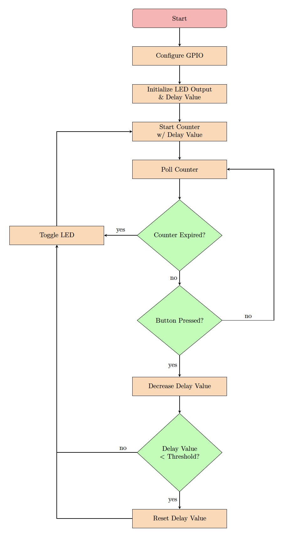
The application in this post adopts the same algorithmic approach as my previous post, however, with minor modifications. Here instead of updating a loop variable to check if it had reached the maximum value I instead poll a timer/counter and check if it reached the desired delay value. Let's incorporate these adjustments into the flow chart to see how it would look now:
🚨 Important Notes:
Delay methods come in two forms, blocking and non-blocking. Blocking means that the controller will sit idle (operations blocked) until the delay finishes. Non-blocking on the other hand means allowing operations to resume and the controller can do other things meanwhile. The code will keep returning to check (poll) the timer if the delay ended. This means that for a polling approach like ours where we need to check on the button being pressed while time passes, a non-blocking approach is required. Again, if we were using interrupts this all wouldn't matter as we would have an interrupt service routine that would inform us that the button got pressed. It's worth noting that interrupts are not affected by blocking delays unless preemption is disabled.
Let's now jump into implementing this algorithm.
👨💻 Code Implementation
📥 Crate Imports
In this implementation, three crates are required as follows:
In this implementation, three crates are required as follows:
The
esp_backtracecrate to define the panicking behavior.The
esp32c3_halcrate to import the ESP32C3 device hardware abstractions.
use esp32c3_hal::{clock::ClockControl, pac::Peripherals, prelude::*, timer::TimerGroup, Rtc, Delay, IO};
use esp_backtrace as _;
📝 Notes
Each of the crate imports needs to have a corresponding dependency in the Cargo.toml file.
Earlier versions of the
esp32c3_halrequired theriscv_rtcrate to be imported for startup code supporting the#[entry]attribute macro. Starting version0.7.0, an#[entry]attribute has been integrated into theesp32c3_hal. This means that an independentriscv_rtimport is not no longer required to support the#[entry]attribute.
🎛 Peripheral Configuration Code
Ahead of our application code, peripherals are configured through the following steps:
1️⃣ Obtain a handle for the device peripherals: In embedded Rust, as part of the singleton design pattern, we first have to take the PAC level device peripherals. This is done using the take() method. Here I create a device peripheral handler named dp as follows:
let peripherals = Peripherals::take();
📝 Note
This is another difference you might note relative to earlier versions of the
esp32c3_hal. In earlier implementationsPeripheralswas imported from thepacmodule, now its imported fromperipheralsinstead. While both use thetakemethod, notice that in the more recent implementation, it does not return aResultso there's no need tounwrap.
2️⃣ Disable the Watchdogs: Just like earlier posts, the ESP32C3 has watchdogs enabled by default and they need to be disabled. If they are not disabled then the device would keep on resetting. To avoid this issue, the following code needs to be included:
let system = peripherals.SYSTEM.split();
let clocks = ClockControl::boot_defaults(system.clock_control).freeze();

// Instantiate and Create Handles for the RTC and TIMG watchdog timers
let mut rtc = Rtc::new(peripherals.RTC_CNTL);
let timer_group0 = TimerGroup::new(peripherals.TIMG0, &clocks);
let mut wdt0 = timer_group0.wdt;
let timer_group1 = TimerGroup::new(peripherals.TIMG1, &clocks);
let mut wdt1 = timer_group1.wdt;
3️⃣ Instantiate and Create Handle for IO: We need to configure the LED pin as a push-pull output and obtain a handler for the pin so that we can control it. We also need to obtain a handle for the button input pin. Before we can obtain any handles for the LED and the button we need to create an IO struct instance. The IO struct instance provides a HAL-designed struct that gives us access to all gpio pins thus enabling us to create handles for individual pins. This is similar to the concept of a split method used in other HALs (more detail here). We do this by calling the new() instance method on the IO struct as follows:
let io = IO::new(peripherals.GPIO, peripherals.IO_MUX);
4️⃣ Obtain a handle for the LED and configure it to output: As earlier stated, the LED is connected to pin 4 (gpio4). As such, we need to create a handle for the LED pin that has gpio4 configured to a push-pull output using the into_push_pull_output() method. We will name the handle led and configure it as follows:
let mut led = io.pins.gpio4.into_push_pull_output();
This HAL documentation page has the full list of methods that the GpioPin type supports.
5️⃣ Obtain a handle and configure the input button: The push button is connected to pin 0 (gpio0) as stated earlier. Additionally, in the pressed state, the button pulls to ground. Also, for the button unpressed state, a pull-up resistor needs to be included so the pin goes high. An internal pull-up can be configured for the pin using the into_pull_up_input() method as follows:
let button = io.pins.gpio0.into_pull_up_input();
Note that as opposed to the LED output, the button handle here does not need to be mutable since we will only be reading it.
6️⃣ Obtain a handle and configure timer: Here we need first need to obtain access to a timer peripheral to access its methods. In the ESP32 a timer exists within what is referred to as a timer group. Note that earlier when disabling the watchdogs in step 2, we actually created a handle for timer_group0 in the statement let timer_group0 = TimerGroup::new(peripherals.TIMG0, &clocks); . As such, all we need to do now is to get access to timer0 and create a handle as follows:
let mut timer0 = timer_group0.timer0;
This will give us access to the timer0 methods.
This is it for configuration. Let's now jump into the application code.
📱 Application Code
Following the design described earlier, I first need to initialize a delay variable del_var and initialize the output of the LED. del_var needs to be mutable as it will be modified by the delay loop. I also choose to set the initial led output level to low by default. Using the same Pin methods mentioned earlier, there is a set_low() method that I use to achieve that.
    // Initialize LED to on or off
    led.set_low().unwrap();

    // Create and initialize a delay variable to manage delay duration
    let mut del_var = 2000_u32.millis();
Notice here that for del_var I am using a Duration type. millis() is a method that converts a number into a Duration.
Next inside the program loop, I first start by kicking off the counter. Examining the timer documentation for methods available there is a start method with the following signature:
fn start<Time>(&mut self, timeout: Time)
where
    Time: Into<<Timer<T> as CountDown>::Time>,
This method kicks off the timer to start counting for a specified timeout duration. The timeout parameter is of a generic type Time . In the application loop, the timer then is kicked off as follows:
timer0.start(del_var);
Following the kick-off of the timer, I now need to keep polling the timer for the elapsed time. As part of the timer available methods, there is a wait method with signature:
fn wait(&mut self) -> Result<(), Error<Void>>
that non-blockingly “waits” until the countdown finishes and returns a Result. If the Result is Ok() then the countdown would have been completed (timer expired). This results in the following application loop:
// Application Loop
loop {
    // Start counter with with del_var duration
    timer0.start(del_var);
    // Enter loop and check for button press until counter reaches del_var
    while timer0.wait() != Ok(()) {
        if button.is_low().unwrap() {
            // If button pressed decrease the delay value by 500 ms
            del_var = del_var - 500_u32.millis();
            // If updated delay value drops below 500 ms then reset it back to starting value to 2 secs
            if del_var.to_millis() < 1000_u32 {
               del_var = 2000_u32.millis();
            }
            // Exit delay loop since button was pressed
            break;
        }
    }
    // Toggle LED
    led.toggle().unwrap();
}
Here you can see that I have created a while loop that keeps polling timer0 until it reaches del_var equivalent to 2 seconds. As indicated in the design section, if the loop ends naturally then del_var remains unchanged. Otherwise, at any point in time while delaying, if the button is pressed I can detect it using the is_low() method. At which point I will be decreasing del_var by 500.millis() duration. If I end up with a del_var value less than 500_u32 then I am restoring the original value I started with of 2001.millis().
🚨 Important Notes:
Same as the past post, once you run the code, you'll see the LED flashing but you'll notice some weird behavior. The flashing frequencies would seem to keep changing in random order. This is because of an effect called "bouncing" on the mechanical button. In Wokwi the bouncing effect can be removed as well. Check the experimentation ideas section below for more detail.
📱 Full Application Code
Here is the full code for the implementation described in this post. You can additionally find the full project and others available on the apollolabs ESP32C3 git repo. Also, the Wokwi project can be accessed here.
#![no_std]
#![no_main]

use esp32c3_hal::{
    clock::ClockControl, peripherals::Peripherals, prelude::*, timer::TimerGroup, Rtc, IO,
};
use esp_backtrace as _;

#[entry]
fn main() -> ! {
    // Take Peripherals, Initialize Clocks, and Create a Handle for Each
    let peripherals = Peripherals::take();
    let system = peripherals.SYSTEM.split();
    let clocks = ClockControl::boot_defaults(system.clock_control).freeze();

    // Instantiate and Create Handles for the RTC and TIMG watchdog timers
    let mut rtc = Rtc::new(peripherals.RTC_CNTL);
    let timer_group0 = TimerGroup::new(peripherals.TIMG0, &clocks);
    let mut wdt0 = timer_group0.wdt;
    let timer_group1 = TimerGroup::new(peripherals.TIMG1, &clocks);
    let mut wdt1 = timer_group1.wdt;

    // Disable the RTC and TIMG watchdog timers
    rtc.swd.disable();
    rtc.rwdt.disable();
    wdt0.disable();
    wdt1.disable();

    // Instantiate and Create Handle for IO
    let io = IO::new(peripherals.GPIO, peripherals.IO_MUX);

    // Instantiate and Create Handle for LED output & Button Input
    let mut led = io.pins.gpio4.into_push_pull_output();
    let button = io.pins.gpio0.into_pull_up_input();

    // Instantiate and Create Handle for Timer
    let mut timer0 = timer_group0.timer0;

    // Initialize LED to on or off
    led.set_low().unwrap();

    // Create and initialize a delay variable to manage delay duration
    let mut del_var = 2000_u32.millis();

    // Application Loop
    loop {
        // Start counter with with del_var duration
        timer0.start(del_var);
        // Enter loop and check for button press until counter reaches del_var
        while timer0.wait() != Ok(()) {
            if button.is_low().unwrap() {
                // If button pressed decrease the delay value by 500 ms
                del_var = del_var - 500_u32.millis();
                // If updated delay value drops below 500 ms then reset it back to starting value to 2 secs
                if del_var.to_millis() < 1000_u32 {
                    del_var = 2000_u32.millis();
                }
                // Exit delay loop since button was pressed
                break;
            }
        }
        // Toggle LED
        led.toggle().unwrap();
    }
}
Conclusion
In this post, an LED control application was created leveraging the GPIO and counter peripherals for the ESP32C3. All code was based on polling (without interrupts) meaning that non-blocking counters were leveraged as well. All code was created at the HAL level using the esp32c3-hal. Have any questions? Share your thoughts in the comments below 👇.