


This blog post is the sixth of a multi-part series of posts where I explore various peripherals in the ESP32C3 using embedded Rust at the HAL level. Please be aware that certain concepts in newer posts could depend on concepts in prior posts.
Prior posts include (in order of publishing):
ESP32 Embedded Rust at the HAL: GPIO Button Controlled Blinking
ESP32 Embedded Rust at the HAL: Button-Controlled Blinking by Timer Polling
ESP32 Embedded Rust at the HAL: Timer Ultrasonic Distance Measurement
Introduction
In this post, I will be configuring and setting up an esp32c3-hal ADC to measure ambient temperature using a 10k NTC Thermistor. Temperature measurements will be continuously collected and sent to the terminal output. For terminal output, I will be leveraging the esp-println crate I started using in the last post. Additionally, I will not be using any interrupts and the example will be set up as a simplex system that transmits in one direction only (towards the terminal/PC).
📚 Knowledge Pre-requisites
To understand the content of this post, you need the following:
Basic knowledge of coding in Rust.
Familiarity with the basic template for creating embedded applications in Rust.
Familiarity with the working principles of NTC Thermistors. This page is a good resource.
💾 Software Setup
All the code presented in this post is available on the apollolabs ESP32C3 git repo. Note that if the code on the git repo is slightly different then it means that it was modified to enhance the code quality or accommodate any HAL/Rust updates.
Additionally, the full project (code and simulation) is available on Wokwi here.
In addition to the above, you would need to install some sort of serial communication terminal on your host PC. Some recommendations include:
For Windows:
For Mac and Linux:
Some installation instructions for the different operating systems are available in the Discovery Book.
🛠 Hardware Setup
Materials
-
A 10k NTC Temperature Sensor.
⚡ Connections
- Temperature sensor signal pin connected to pin gpio1. In Wokwi this is a direct connection. However, if you have the individual NTC component, you need to set it up in a voltage divider configuration with a 10K resistor (circuit in next section).
🔌 Circuit Analysis
The temperature sensor used is a negative temperature coefficient (NTC) sensor. This means the resistance of the sensor increases as the temperature increases. The following figure shows the schematic of the temperature sensor circuit:
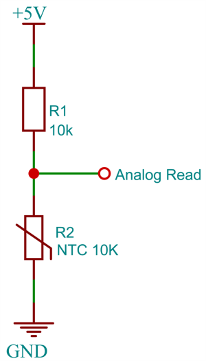
It is shown that the NTC Thermistor is connected in a voltage divider configuration with a 10k resistor. As such, the voltage at the positive terminal of the op-amp \( V_{\+} \) is equal to the voltage on the signal terminal and expressed as:
$$V_{\text{+}} = V_{cc}* \frac{R_{1}}{R_{1}} + R_{\text{NTC}}$$
Where \(R_1 = 10k\Omega\) and the resistance value of \(R_{\text{NTC}}\) is the one that needs to be calculated to obtain the temperature. This means that later in the code, I would need to retrieve back the value of \(R_{\text{NTC}}\) from the \(V_{\text{+}}\) value that is being read by the ADC. With some algebraic manipulation, we can move all the known variables to the right-hand side of the equation to reach the following expression:
$$R_{\text{NTC}} = \left( \frac{ V_{cc} }{ V_{\text{+}} } -1 \right) * R_{1}$$
After extracting the value of \(R_{\text{NTC}}\), I would need to determine the temperature. Following the equations in the datasheet, I leverage the Steinhart-Hart NTC equation that is presented as follows:
\[\beta = \frac{ln(\frac{R\_{\text{NTC}}}{R_0})}{(\frac{1}{T}-\frac{1}{T_0})}\]
where \( \beta \) is a constant and equal to 3950for our NTC as stated by Wokwi and \( T \) is the temperature we are measuring. \( T_0 \) and \( R_0 \) refer to the ambient temperature (typically 25 Celcius) and nominal resistance at ambient temperature, respectively. The value of the resistance at 25 Celcius ( \( T_0 \) ) is equal to \(10k\Omega\) ( \( R_0 \) ). With more algebraic manipulation we solve for \( T \) to get:
\[T = \frac{1}{\frac{1}{\beta} * ln(\frac{R\_{\text{NTC}}}{R_0}) +\frac{1}{T_0}}\]
👨🎨 Software Design
Now that we know the equations from the prior section, an algorithm needs to be developed and is quite straightforward in this case. After configuring the device, the algorithmic steps are as follows:
Kick off the ADC and obtain a reading/sample.
Calculate the temperature in Celcius.
Print the temperature value on the terminal.
Go back to step 1.
👨💻Code Implementation
📥 Crate Imports
In this implementation, the following crates are required:
The
esp32c3_halcrate to import the ESP32C3 device hardware abstractions.The
esp_backtracecrate to define the panicking behavior.The
esp_printlncrate to provideprintln!implementation.The
libmcrate to provide an implementation for a natural logarithm.
use esp32c3_hal::{
    clock::ClockControl, peripherals::Peripherals, prelude::*, systimer::SystemTimer,
    timer::TimerGroup, Delay, Rtc, IO,
};
use esp_backtrace as _;
use esp_println::println;
use libm::log;
🎛 Initialization/Configuration Code
⌨️ GPIO Peripheral Configuration:
1️⃣ Obtain a handle for the device peripherals: In embedded Rust, as part of the singleton design pattern, we first have to take the PAC-level device peripherals. This is done using the take() method. Here I create a device peripheral handler named dp as follows:
let peripherals = Peripherals::take();
2️⃣ Disable the Watchdogs: The ESP32C3 has watchdogs enabled by default and they need to be disabled. If they are not disabled then the device would keep on resetting. To avoid this issue, the following code needs to be included:
let system = peripherals.SYSTEM.split();
let clocks = ClockControl::boot_defaults(system.clock_control).freeze();

// Instantiate and Create Handles for the RTC and TIMG watchdog timers
let mut rtc = Rtc::new(peripherals.RTC_CNTL);
let timer_group0 = TimerGroup::new(peripherals.TIMG0, &clocks);
let mut wdt0 = timer_group0.wdt;
let timer_group1 = TimerGroup::new(peripherals.TIMG1, &clocks);
let mut wdt1 = timer_group1.wdt;
3️⃣ Instantiate and Create Handle for IO: We need to configure the NTC pin as an analog input and obtain a handler for the pin so that we can control it. This will be done in the following step. Though before we can obtain any handles for the NTC and the button we need to create an IO struct instance. The IO struct instance provides a HAL-designed struct that gives us access to all gpio pins thus enabling us to create handles for individual pins. This is similar to the concept of a split method used in other HALs (more detail here). We do this by calling the new() instance method on the IO struct as follows:
let io = IO::new(peripherals.GPIO, peripherals.IO_MUX);
4️⃣ Configure and Create Handle for Analog Pin: Similar to how pins were configured before with gpio, there is instead an into_analog() method that configures the pin as an analog pin. An ntc_pin handle is created to gpio1 to and analog pin as follows:
let ntc = io.pins.gpio1.into_analog();
ADC Peripheral Configuration:
1️⃣ Obtain a handle for ADC configuration: To configure an analog pin in the esp32c3-hal, first, an ADC configuration instance needs to be created. The same configuration instance is then later used to both enable the analog pin and create an ADC instance. As such, an adc_config handle is created using the AdcConfig type new method as follows:
// Create handle for ADC configuration parameters
let mut adc_config = AdcConfig::new();
2️⃣ Obtain a handle and enable the analog pin: In order to enable the analog ntc_pin pin, the AdcConfig type has an enable_pin method that takes two arguments. The first argument is the analog gpio pin, and the second is an Attenuation enum specifying the desired level of attenuation:
let mut adc_pin =
        adc_config.enable_pin(
           ntc,
           Attenuation::Attenuation11dB
        );
3️⃣ Obtain a handle and Configure an ADC instance: Before creating an ADC instance, similar to some other peripherals, the peripheral needs to be promoted to HAL-level structs. This is done using the split method on the APB_SARADC peripheral type (if not familiar, read this past post of mine explaining split and constrain methods) as follows:
// Promote ADC peripheral to HAL-level Struct
let analog = peripherals.APB_SARADC.split();
Now that the peripheral is split, we have access to the individual ADC to pass to an ADC instance. As a result, to create an ADC instance there is an adc method as part of the ADC type in the esp32c3-hal. The adc method takes three arguments, a peripheral clock controller instance (accessed via the system handle), an ADC instance (accessed via the analog handle), and an ADC configuration instance (the adc_config handle):
let mut adc = ADC::adc(
    &mut system.peripheral_clock_control,
    analog.adc1,
    adc_config,
)
.unwrap();
This is it for configuration! Let's now jump into the application code.
📱Application Code
Following the design described earlier, before entering my loop, I first need to set up a couple of constants that I will be using in my calculations. This includes keying in the constant values for \( \beta \) and \(R_0\) as follows:
const B: f64 = 3950.0; // B value of the thermistor
const R0: f64 = 10000.0; // Nominal NTC Value
After entering the program loop, as the software design stated earlier, first thing I need to do is kick off the ADC to obtain a sample/reading. This is done through the read method that takes a mutable reference to the adc_pin instance and returns a Result:
let sample: u16 = adc.read(&mut adc_pin).unwrap();
Next, I convert the sample value to a temperature by implementing the earlier derived equations as follows:
let temperature = 1. / (log(1. / (4096. / sample as f64 - 1.)) / B + 1.0 / 298.15) - 273.15;
A few things to note here; first I don't convert the collected sample to value to a voltage as in the first calculation the voltage calculation is a ratio. This means I keep the sample in LSBs and use the equivalent LSB value for \(V_{cc}\). To plug in \(V_{cc}\) I simply calculate the maximum possible LSB value (upper reference) that can be generated by the ADC. This is why I needed to know the resolution, which was 12 because \(V_{cc} = 2^{12} LSBs\). Second, recall from the read method that sample is a u16, so I had to use as f64 to cast it as an f64 for the calculation. Third, log is the natural logarithm obtained from the libm library that I imported earlier. Fourth, and last, the temperature is calculated in Kelvins, the 273.15 is what converts it to Celcius.
Finally, now that the temperature is available, I send it over to the console using the println! macro as follows:
println!("Temperature {:02} Celcius\r", temperature);
This is it!
📱Full Application Code
Here is the full code for the implementation described in this post. You can additionally find the full project and others available on the apollolabs ESP32C3 git repo. Also the Wokwi project can be accessed here.
#![no_std]
#![no_main]

use esp32c3_hal::{
    adc::{AdcConfig, Attenuation, ADC},
    clock::ClockControl,
    peripherals::Peripherals,
    prelude::*,
    timer::TimerGroup,
    Rtc, IO,
};
use esp_backtrace as _;
use esp_println::println;
use libm::log;

#[entry]
fn main() -> ! {
    // Take Peripherals, Initialize Clocks, and Create a Handle for Each
    let peripherals = Peripherals::take();
    let mut system = peripherals.SYSTEM.split();
    let clocks = ClockControl::boot_defaults(system.clock_control).freeze();

    // Instantiate and Create Handles for the RTC and TIMG watchdog timers
    let mut rtc = Rtc::new(peripherals.RTC_CNTL);
    let timer_group0 = TimerGroup::new(peripherals.TIMG0, &clocks);
    let mut wdt0 = timer_group0.wdt;
    let timer_group1 = TimerGroup::new(peripherals.TIMG1, &clocks);
    let mut wdt1 = timer_group1.wdt;

    // Disable the RTC and TIMG watchdog timers
    rtc.swd.disable();
    rtc.rwdt.disable();
    wdt0.disable();
    wdt1.disable();

    // Instantiate and Create Handle for IO
    let io = IO::new(peripherals.GPIO, peripherals.IO_MUX);

    // Create ADC Instance
    // Create handle for ADC configuration parameters
    let mut adc_config = AdcConfig::new();
    // Configure ADC pin
    let mut adc_pin =
        adc_config.enable_pin(io.pins.gpio1.into_analog(), Attenuation::Attenuation11dB);
    // Promote ADC peripheral to HAL-level Struct
    let analog = peripherals.APB_SARADC.split();
    // Create handle for ADC, configuring clock, and passing configuration handle
    let mut adc = ADC::adc(
        &mut system.peripheral_clock_control,
        analog.adc1,
        adc_config,
    )
    .unwrap();

    const B: f64 = 3950.0; // B value of the thermistor
    const R0: f64 = 10000.0; // Nominal NTC Value

    // Algorithm
    // 1) Get adc reading
    // 2) Convert to temperature
    // 3) Send over Serial
    // 4) Go Back to step 1

    // Application
    loop {
        // Get ADC reading
        let sample: u16 = adc.read(&mut adc_pin).unwrap();
        // For blocking read
        // let sample: u16 = nb::block!(adc.read(&mut adc_pin)).unwrap();

        //Convert to temperature
        let temperature = 1. / (log(1. / (4096. / sample as f64 - 1.)) / B + 1.0 / 298.15) - 273.15;

        // Print the temperature output
        println!("Temperature {:02} Celcius\r", temperature);
    }
}
Conclusion
In this post, an analog temperature measurement application was created leveraging the ADC peripheral for the ESP32C3. The resulting measurement is also sent over to terminal output. All code was based on polling (without interrupts). Additionally, all code was created at the HAL level using the esp32c3-hal. Have any questions? Share your thoughts in the comments below 👇.