


This blog post is the sixth of a multi-part series of posts where I explore various peripherals in the STM32F401RE microcontroller using embedded Rust at the HAL level. Please be aware that certain concepts in newer posts could depend on concepts in prior posts.
Prior posts include (in order of publishing):
Introduction
In this post, I will be using the stm32 embassy hal to configure and set up timer and GPIO peripherals with an ultrasonic sensor to measure obstacle distance. A distance measurement will be continuously collected and sent to a PC terminal over UART. Additionally, I will not be using any interrupts and the example will be set up as a simplex system that transmits in one direction only (towards the PC). This example is an embassy rewrite of the example previously written with the stm32f4xx-hal in this post. This post is mostly self-contained so there is no need to refer back to the older post unless one would like to compare.
📚 Knowledge Pre-requisites
To understand the content of this post, you need the following:
Basic knowledge of coding in Rust.
Familiarity with the basic template for creating embedded applications in Rust.
Familiarity with UART communication basics.
Familiarity with working principles of Ultrasonic sensors. This page is a good resource.
💾 Software Setup
All the code presented in this post in addition to instructions for the environment and toolchain setup is available on the apollolabsdev Nucleo-F401RE git repo. Note that if the code on the git repo is slightly different then it means that it was modified to enhance the code quality or accommodate any HAL/Rust updates.
In addition to the above, you would need to install some sort of serial communication terminal on your host PC. Some recommendations include:
For Windows:
For Mac and Linux:
Apart from Serial Studio, some detailed instructions for the different operating systems are available in the Discovery Book.
For me, Serial Studio comes highly recommended. I personally came across Serial Studio recently and found it to be awesome for two main reasons. First is that you can skip many of those instructions for other tools, especially in Mac and Linux systems. Second, if you are you want to graph data over UART, it has a really nice and easy-to-configure setup. It's also open-source and free to use.
🛠 Hardware Setup
👔 Materials
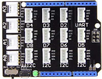
- Seeed Studio Grove Base Shield V2.0
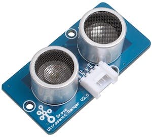
- Seeed Studio Grove Ultrasonic Distance Sensor. The module uses the NU40C16T/R-1 Ultrasonic Sensor.
🚨 Important Note:
I used the Grove modular system for connection ease. It is a more elegant approach and less prone to mistakes. One can directly wire the ultrasonic sensor to the board if need be.
🔌 Connections
Ultrasonic echo pin connected to pin PA8 (Grove Connector D7).
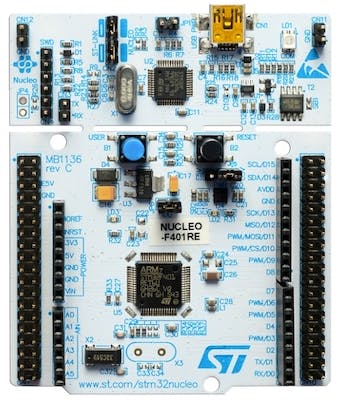
The UART Tx line that connects to the PC through the onboard USB bridge is via pin PA2 on the microcontroller. This is a hardwired pin, meaning you cannot use any other for this setup. Unless you are using a different board other than the Nucleo-F401RE, you have to check the relevant documentation (reference manual or datasheet) to determine the number of the pin.
👨🎨 Software Design
The ultrasonic sensor used is a single-pin interface sensor. The single pin, referred to as the echo pin, operates in a bidirectional mode. The echo pin, first operating as an input, should be triggered by a pulse that is at least 10us wide. This would cause the sensor to emit a series of ultrasonic pulses and measure their propagation delay. After that, the echo pin switches to an output providing a pulse width proportional to the distance of the obstacle.
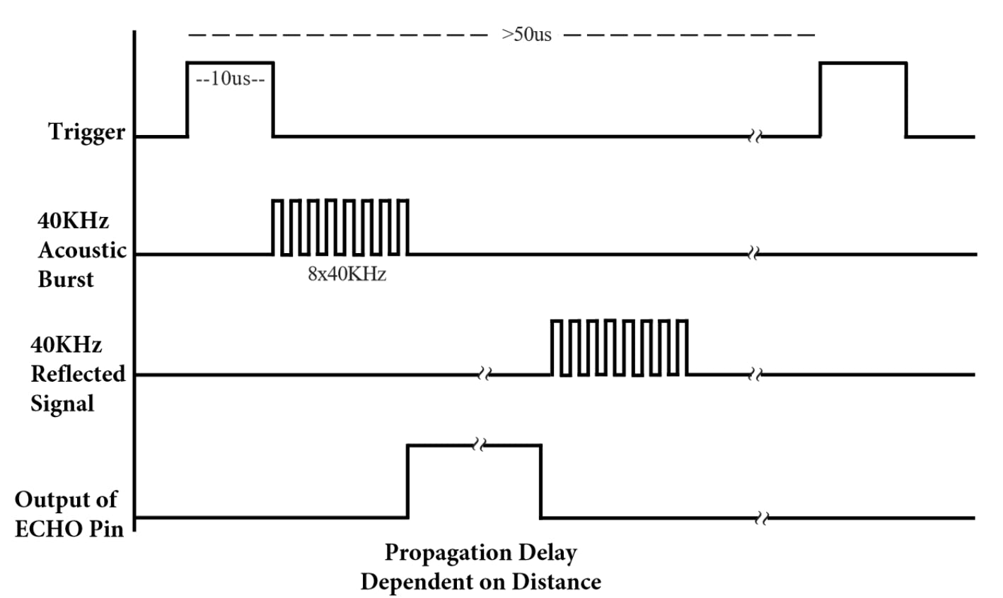
The obstacle distance is calculated as:
$$\text{distance}{(cm)}=\frac{\text{echo pulse width}{(us)}}{29*2}$$
After the above definition, defining the algorithm becomes direct. As such, after configuring the device, the algorithmic steps are as follows:
Set PA8 pin output to low for 5 us to get a clean low pulse
Set PA8 pin output to high (trigger) for 10us
Switch PA8 to an input
Keep polling PA8 input until it goes high
Once the PA8 input goes high kick-off counter/timer
Keep polling PA8 input until it goes low
Obtain pulse duration measurement from counter/timer
Calculate the distance and send the result to the UART serial channel
Go back to 1
👨💻 Code Implementation
📥 Crate Imports
In this implementation, the following crates are required:
The
cortex_m_rtcrate for startup code and minimal runtime for Cortex-M microcontrollers.The
cortex_mcrate to import Cortex-M microcontroller abstractions. These will be needed for using blocking delay.The
core::fmtcrate will allow us to use thewriteln!macro for easy printing.The
heaplesscrate to import and create a fixed capacityString.The
embassy_timecrate to import timekeeping capabilities.The
embassy_stm32crate to import the embassy STM32 series microcontroller device hardware abstractions. The needed abstractions are imported accordingly.The
panic_haltcrate to define the panicking behavior to halt on panic.
use core::fmt::Write;
use cortex_m::prelude::_embedded_hal_blocking_delay_DelayUs;
use heapless::String;

use cortex_m_rt::entry;
use embassy_stm32::dma::NoDma;
use embassy_stm32::gpio::{Flex, Pull, Speed};
use embassy_stm32::usart::{Config, UartTx};
use embassy_time::{Delay, Instant};
use panic_halt as _;
🎛 Peripheral Configuration Code
Initialize MCU and obtain a handle for the device peripherals: Ahead of configuring any peripheral a device peripheral handler p needs to be created:
let p = embassy_stm32::init(Default::default());
GPIO Peripheral Configuration
Configure and Obtain Handle for GPIO Ultrasonic Echo Pin: I need to configure the echo pin as input in the beginning and obtain a handler for the pin so that I can control it. Since I'm going to be switching the pin back and forth from input to output, I cannot use the existing Input and Output types. Instead in the API reference, there is a Flex type that is defined as a GPIO flexible pin. A Flex pin can dynamically be switched between input and output modes. To create an instance of PA8 that will be connected to the ultrasonic sensor, a echo handle is created using the new method in Flex as follows:
let mut echo = Flex::new(p.PA8);
UART Peripheral Configuration
Obtain Handle and Configure UART peripheral: UART is configured similar to the embassy UART post such that it can send data in a single direction to a host PC. A handle usart is created as follows:
let mut usart = UartTx::new(p.USART2, p.PA2, NoDma, Config::default());
Additional to the usart handle, an empty String handle msg is instantiated to later store the contents sent over UART:
let mut msg: String<64> = String::new();
Timer and Delay Peripheral Configuration:
Obtain handle for blocking delay: In the algorithm, there is a step where I have to provide a pulse trigger that is 10us wide. For that, I would need to use some delay method to keep the echo pin high for that duration. This can be handled by creating a blocking delay handle delay as follows:
let mut delay = Delay;
This is it for configuration! Let's now jump into the application code.
📱 Application Code
Following the design described earlier, I first need to set the echo pin output to low for 5 us to get a clean low pulse. However, according to the documentation, the echo pin initial output level is unspecified since its instantiated as a Flex. As a result, the mode of the pin needs to be defined before it is used. In the Flex API reference there is a set_as_output method that will configure the pin as an output. The set_as_output method only requires that the Speed of the pin is passed as an argument:
echo.set_as_output(Speed::Low);
After that, the pin output needs to be set to low for 5 us:
echo.set_low();
delay.delay_us(5_u32);
Step 2 in the algorithm requires that I set the echo pin output to high (trigger) for 10us:
echo.set_high();
delay.delay_us(10_u32);
Step 3 in the algorithm requires that I set the echo pin back to an input. This can be done exactly in the same manner as earlier, however using the set_as_input method. Compare to the set_as_ouput method, set_as_input requires instead that the Pull of the pin is passed as an argument:
echo.set_as_input(Pull::None);
Next I need to keep polling the echo pin until it goes high marking the start of the echo pulse. This is done as follows:
while !(echo.is_high()) {}
Using the while loop and the is_high Flex method, the code is going around this same line until the echo pin input goes high.
Afterward, a timer needs to be kicked off to measure the pulse width. From the embassy_time crate, an Instant type can be used to determine a Duration. In order to do that, two Instants need to be collected to calculate a duration. As such, to kick off a measurement, a current Instant needs to be captured. This is done using the now instance method. As a result, I create an inst handle to capture the starting Instant for the measurement as follows:
let inst = Instant::now();
After that, I wait until the echo pin goes low:
while !(echo.is_low()) {}
Once the echo goes low, the current Instant needs to be collected and the Duration calculated. The API reference provides a checked_duration_since instance method that takes a reference to the current Instance and a prior Instance (inst in our case) as arguments and returns a Duration wrapped in an Option. The duration is captured in a duration variable as follows:
let duration = Instant::checked_duration_since(&Instant::now(), inst).unwrap();
Since the Duration is wrapped in an Option then it needs to be unwrap ped to recover the value. Now that the pulse duration is available, a distance can be calculated. Using the earlier presented formula, the distance in centimeters is calculated using the following code:
let distance_cm = duration.as_micros() / 2 / 29;
as_micros is a Duration method provided in the API reference that converts the Duration to an integer number of microseconds.
Finally, the result is sent over UART using the writeln! macro and the USART blocking_write method:
core::writeln!(&mut msg, "Distance {:02} cm\r", distance_cm).unwrap();
usart.blocking_write(msg.as_bytes()).unwrap();
msg.clear();
If you have noticed, writeln! takes three parameters where the third parameter contains the distance_cm variable that was created earlier to store the result of the distance calculation.
📀 Full Application Code
Here is the full code for the implementation described in this post. You can additionally find the full project and others available on the apollolabsdev Nucleo-F401RE git repo.
#![no_std]
#![no_main]
#![feature(type_alias_impl_trait)]

use core::fmt::Write;
use cortex_m::prelude::_embedded_hal_blocking_delay_DelayUs;
use heapless::String;

use cortex_m_rt::entry;
use embassy_stm32::dma::NoDma;
use embassy_stm32::gpio::{Flex, Pull, Speed};
use embassy_stm32::usart::{Config, UartTx};
use embassy_time::{Delay, Instant};
use panic_halt as _;

#[entry]
fn main() -> ! {
    // Initialize and create handle for devicer peripherals
    let p = embassy_stm32::init(Default::default());

    let mut echo = Flex::new(p.PA8);

    //Configure UART
    let mut usart = UartTx::new(p.USART2, p.PA2, NoDma, Config::default());

    // Create empty String for message
    let mut msg: String<64> = String::new();

    // Delay Handle
    let mut delay = Delay;

    // Algorithm
    // 1) Set pin ouput to low for 5 us to get clean low pulse
    // 2) Set pin output to high (trigger) for 10us
    // 3) Switch back to input
    // 4) Keep checking if pin goes high
    // 5) Once pin goes high start kick off counter/timer
    // 6) Wait for Pin to go low
    // 7) Obtain pulse measurement from timer
    // 8) Print out measurement on Serial
    // 9) Go back to 1)

    // Application Loop
    loop {
        // 1) Set pin ouput to low for 5 us to get clean low pulse
        echo.set_as_output(Speed::Low);
        echo.set_low();
        delay.delay_us(5_u32);

        // 2) Set pin output to high (trigger) for 10us
        echo.set_high();
        delay.delay_us(10_u32);

        // 3) Switch back to input
        echo.set_as_input(Pull::None);

        // Wait until pin goes high
        while !(echo.is_high()) {}

        // Kick off timer measurement by capturing current instant
        let inst = Instant::now();

        // Wait until pin goes low.
        while !(echo.is_low()) {}

        // Stop timer and collect elapsed time
        let duration = Instant::checked_duration_since(&Instant::now(), inst).unwrap();

        // Calculate the distance in cms using formula in datasheet
        let distance_cm = duration.as_micros() / 2 / 29;

        // Send calculated distance to serial interface
        core::writeln!(&mut msg, "Distance {:02} cm\r", distance_cm).unwrap();
        usart.blocking_write(msg.as_bytes()).unwrap();
        msg.clear();
    }
}
Conclusion
In this post, an ultrasonic distance measurement application was created leveraging the GPIO and Counter peripherals for the STM32F401RE microcontroller on the Nucleo-F401RE development board. The resulting measurement is also sent over to a host PC over a UART connection. All code was based on polling (without interrupts). Additionally, all code was created at the HAL level using the STM32 Embassy HAL. Have any questions? Share your thoughts in the comments below 👇.